
Operating Instructions and Installation Instructions


2922
3
GB
3. INSTALLATION
THE BURNER MUST BE INSTALLED IN CONFORMITY WITH LEGISLATION AND LOCAL STANDARDS.
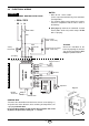
3.1 BOILER FIXING
➤
Insert the recirculating pipe (1) on the burner blast tube (2) and fix it with the screw (3), (see fig. 2).
Attention:
respect the dimensions, as described in chapter “2.2 OVERALL DIMENSIONS“ at page 2.
➤
Put on the flange (4) the screw and two nuts, (see fig. 4).
➤
Widen, if necessary, the insulating gasket holes (5), (see fig. 5).
➤
Fix the flange (4) to the boiler door (6) using screws (7) and
(if necessary)
the nuts (8)
interposing the
insulating gasket (5)
, (see fig. 3).
3.2 FUEL SUPPLY
The burner is designed to allow entry of the oil supply pipes on either side.
Depending on the oil supply pipes position (to the right or to the left hand side of the burner) the fixing plate
(1)
and closing plate
(2)
should be reversed, (see fig. 6).
S7708
D5012
Fig. 5
Fig. 2
3
2
1
4
4
8
5
7
Fig. 4
6
7
Fig. 3
E9163
S7709
Boiler door must have a max. thickness
of 80 mm, refractory linig included.
IMPORTANT
D5700
21 1
Fig. 6