
Specifications


molbox™ RFM™ OPERATION AND MAINTENANCE MANUAL
© 1998-2007 DH Instruments, a Fluke Company Page 44
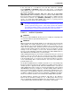
1. High Isolation: Open
2. Low Isolation: Closed
3. Bypass: Open
4. Mirorange Bypass: Open
Figure 6. molbox RFM
Internal Pneumatic Schematic – TARING molbloc-S OPERATION
OPERATION
To access the TARE function press [TARE], <1tare>. The display is:
1. The current pressure read by the upstream
(left) and downstream (right) RPTs without
taking into account the current tare value.
These are untared readings in the current
pressure units.
2. <T>, to indicate that this is a TARE display
showing the tare between the two absolute
RPTs.
3. The difference between the untared upstream
and downstream absolute pressure readings
(upstream – downstream). This differential
value is always in Pascal [Pa].
4. Tare message
<OK> If tare is less than 300 Pa,
<CHECK> if tare is between 300 and 1250 Pa
<NEED CAL> if tare is greater than 1250 kPa
201.032 kPa ^201.013
T 19.3 Pa OK
The tare screen shows the upstream and downstream RPT readings
WITHOUT the current tare applied. The [P&T] screen shows the RPT readings
WITH the tare applied (see Section
3.4.5).
3.4.4.2 <2Purge>
PURPOSE
To purge the lines between the molbloc and the molbox RFM and the internal
molbox RFM volumes of one gas with another gas by setting up an internal
valving configuration in which gas flows through the molbox RFM.
PRINCIPAL
molbox RFM supports the measurement of flow of a variety of gases. To
calculate the flow, the thermodynamic characteristics of the gas must be known.
These are stored in molbox RFM memory. For the flow to be calculated
correctly, the gas flowing through the molbloc must be the gas that is selected on