
Instruction Manual


Regency Bellavista™ B41XTCE Gas Fireplace
19
INSTALLATION
VENT RESTRICTOR & BAFFLE INSTALLATION
NOTE: THE VENT RESTRICTOR & BAFFLE MUST BE INSTALLED PRIOR TO OPTIONAL PANEL INSTALLATION.
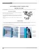
Diagram 2: Vent Restrictor installed on
Top Exhaust Assembly
6) From inside the fi rebox, install the baffl e plate with 4 - 1/4" x 1/2 "
screws. Ensure all screws are tightly secure, but do not over tighten.
1) Determine the venting confi guration.
2) Go to venting arrangements section to determine if a vent restrictor
setting is required.
Note: The vent restrictor does not apply to rear vent applications.
3) Remove baffl e plate. See Diagram 3.
4) Align the vent restrictor plate to the required vent restrictor position
as per diagram 1.
5) Once the vent restrictor plate is in the required position, secure with
2 - 1/4" x 1/2" screws. Ensure all screws are tight, but do not over
tighten. (See diagram 2).
SET 3
THIS HOLE SETS THE
VENT RESTRICTOR
AT 1-1/2”
SET 2
THIS HOLE SETS THE
VENT RESTRICTOR
AT 2-1/2”
SET 1
THIS HOLE SETS THE
VENT RESTRICTOR
AT 3-1/2”
NO VENT RESTRICTOR
Factory setting
Baffl e Plate
Diagram 3
Diagram 1
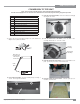
VENTING INTRODUCTION
The B41XTCE uses the "balanced fl ue" technology Co-Axial system. The inner liner vents products of combustion to the outside while the outer
liner draws outside combustion air into the combustion chamber thereby eliminating the need to use heated room air for combustion and losing
warm room air up the chimney.
Note: These fl ue pipes must not be connected to any other appliance.
The gas appliance and vent system must be vented directly to the outside of the building, and never be attached to a chimney serving a separate
solid fuel or gas burning appliance. Each direct vent gas appliance must use it's own separate vent system. Common vent systems are prohibited.