
Quick Start Guide


Wiring:
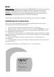
1. Mount Illuminator
2. Connect Illuminator to low voltage input 12-24V AC/DC
IMPORTANT: For Vario 16 variants : 24V only AC/DC
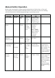
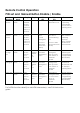
3. Complete configuration, wiring and final set-up using manual push buttons on
the illuminator or VARIO Remote Controller (VRC) - VRC is an optional
accessory
Black Wire = Negative (-ve)
Red Wire = Positive (+ve)
White & Yellow wires = Photocell following contact, Volt free output, Non polarity
sensitive
Orange and Purple Wires = Telemetry input Volt free / dry contact or TTL input
Lens Selection:
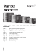
VARIO is factory set and delivered with a 35˚ beam width angle.
To alter to 10˚, simply remove interchangeable lens (ILS).
To alter to 60˚, replace with other ILS lens supplied.
Other angle ILS lenses are available to order: 80˚ and 120˚.
Please handle ILS lenses with care – and do not touch optical film.
Use 2.5mm Allen/hex key. Re-attach base plate securely ensuring gasket is correctly
located.
Important Note : Ensure base plate is securely located, the gasket is
correctly located and the screws correctly fastened to ensure and
maintain IP66 rating of the product