
User guide


Manual-3
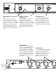
Power ON switch and LED
Your basic, straightforward power
switch. When the yellow LED is lit, the
SAC 22 is ready to go.
LOW/HIGH FREQUENCY control
This 31-position selector sets the
crossover frequency between the Low
and High frequency Outputs in both
Channels. Consult the manuafacturer of
the drivers or cabinets for the correct
setting.
HIGH LEVEL control
This controls the level of signal
going to the HIGH OUTPUT jacks.
Unity gain is reached at the “0 dB”
mark with the INPUT LEVEL set to
“10”. Refer to Operating Instructions on
page Manual-6.
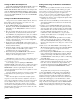
INPUTS
These are balanced Inputs. It is best
to use balanced lines, especially when
connecting cables over 10 feet in length.
If you are feeding the SAC 22 from a
device that does not have balanced XLR
connectors, consult SOUND SYSTEM
INTERCONNECTION on page
Manual-10.
MONO SUB OUTPUT and
100 Hz FILTER switch
This Output contains the summed
signals of the LEFT and RIGHT LOW
OUTPUTS. It may be used instead of,
or along with the LOW OUTPUTS.
Switch the 100 Hz FILTER to IN for
best results when using a subwoofer
along with the LOW OUTPUTS. This
sends only the very lowest frequencies
to the subwoofer. With the switch OUT,
the MONO SUB OUT still produces the
summed LOW OUTPUTS without the
100 Hz FILTER.
Cable Wiring
In agreement with IEC and AES/
ANSI standards, Rane wiring conven-
tion is pin 2 Positive (hot), pin 3
Negative (cold or return), and pin 1
signal grounded and chassis grounded
(to allow unbalanced operation). The
XLR case is chassis grounded. This
device uses low impedance balanced
line drivers. Do not connect the “+” or
“–” output pins to ground, as this may
cause the power supply to shut down.
For unbalanced use, leave the unused
output pin (“+” or “–”) unterminated.