
Owner's manual


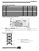

Table Of Contents
- Features
- Description
- Pin Configurations
- Block Diagram
- Device Operation
- Absolute Maximum Ratings*
- DC and AC Operating Range
- Operating Modes
- DC Characteristics
- AC Read Characteristics
- AC Read Waveforms
- Input Test Waveforms and Measurement Level
- Output Test Load
- Pin Capacitance
- AC Byte Load Characteristics
- AC Byte Load Waveforms(1)(2)
- Program Cycle Characteristics
- Software Protected Program Waveform
- Programming Algorithm(1)
- Data Polling Characteristics(1)(2)
- Data Polling Waveforms
- Toggle Bit Characteristics(1)
- Toggle Bit Waveforms(1)(3)
- Software Product Identification Entry(1)
- Software Product Identification Exit(1)
- Boot Block Lockout Feature Enable Algorithm(1)
- Ordering Information
- Packaging Information

6
AT29BV020
0402D–FLASH–05/02
AC Read Waveforms
Notes: 1. CE may be delayed up to t
ACC
-t
CE
after the address transition without impact on t
ACC
.
2. OE
may be delayed up to t
CE
-t
OE
after the falling edge of CE without impact on t
CE
or by t
ACC
-t
OE
after an address change
without impact on t
ACC
.
3. t
DF
is specified from OE or CE whichever occurs first (CL = 5 pF).
4. This parameter is characterized and is not 100% tested.
AC Read Characteristics
Symbol Parameter
AT29BV020-12 AT29BV020-15
AT29BV020-25 AT29BV020-35
UnitsMin Max Min Max
Min Max Min Max
t
ACC
Address to Output Delay 120 150 250 350 ns
t
CE
(1)
CE to Output Delay 120 150 250 350 ns
t
OE
(2)
OE to Output Delay 0 50 0 70 0 120 0 150 ns
t
DF
(3)(4)
CE or OE toOutputFloat 0300400 60 0 75 ns
t
OH
Output Hold from OE,CEor
Address, Whichever Occurred First
000 0 ns
Note:
Not recommended for New Designs.