
Product Info


Smart LTE Module Series
SC20 Hardware Design
SC20_Hardware_Design 83 / 130
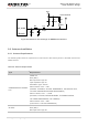
Active Antenna
VCC
Module
ANT_GNSS
56nH
10R
1uF
100pF
NM
NM
C4
C1
R1
L1
R2
0R
C5
C3
C2
100pF
Figure 38: Reference Circuit Design for GNSS Active Antenna
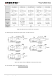
6.4. Antenna Installation
6.4.1. Antenna Requirements
The following table shows the requirement on main antenna, RX-diversity antenna, Wi-Fi/BT antenna and
GNSS antenna.
Table 40: Antenna Requirements
Type
Requirements
GSM/WCDMA/TD-SCDMA/
LTE
VSWR: ≤ 2
Gain (dBi): 1
Max Input Power (W): 50
Input Impedance (Ω): 50
Polarization Type: Vertical
Cable Insertion Loss: < 1dB
(GSM850, EGSM900, WCDMA B5/B6/B8/B19, EVDO/CDMA BC0,
LTE-FDD B5/B8/B12/B13/B18/B19/B20/B26/B28)
Cable Insertion Loss: < 1.5dB
(DCS1800, PCS1900, WCDMA B1/B2/B4, TD-SCDMA B34/B39,
LTE-FDD B1/B2/B3/B4/B25, LTE-TDD B39)
Cable Insertion Loss: < 2dB
(LTE-FDD B7, LTE-TDD B38/B40/B41)
Wi-Fi/BT
VSWR: ≤ 2
Gain (dBi): 1
Max Input Power (W): 50