
Owner's Manual


10
EN
GPIO Connector
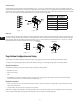
The Page Station rear panel includes a six-terminal receptacle (Figure 10, and Figure 12) that provides various GPIO (General Purpose Inputs and
Outputs) that allows the Page Station to control or be controlled by a variety of external products. The Page Station GPIO receptacle accepts Euro style
(Phoenix) two, three or six-terminal plugs. A six-terminal plug is included in the Page Station ship kit. Follow the Page Station rear panel pin out labels
(Table 1) when connecting to the GPIO receptacle. Refer to the Q-Sys online help for GPIO details.
LINE OUT
The Page Station rear panel includes an auxiliary Line Output receptacle to drive an amplifier or console input directly. The Line Output may be used
for mission critical or alternative event applications. The receptacle accept a Euro style (Phoenix) three-terminal plug, which are included in the Page
Station package. Follow the Page Station rear panel pin-out labels (Figure 12) when connecting to the receptacle. Figure 13 and Figure 14 indicate
appropriate termination practices for balanced and unbalanced applications.
Page Station Configuration and Setup
Q-Sys Designer is the software application required to configure your paging system. Refer to the Q-Sys Designer online help for details.
This section covers connecting the hardware to the Q-LAN network, powering up, and re-setting the Page Station to the factory defaults.
Optional Connections
The following are optional, and should be connected prior to powering up the Page Station.
• MIC/LINE (3-Pin Euro)
• LINE OUT (3-Pin Euro)
• GPIO
• AUX POWER (If you make this connection and plan to use PoE, do not turn the auxiliary power supply on until you have made the network
connection with PoE turned on. See About PoE and AUX POWER, page 11)
Required Connections
• LAN-A — Connect one end of a CAT-5e cable with an RJ45 connector to the LAN-A connector on the Page Station. Connect the other end of the
cable to the Q-LAN network.
• Connect LAN-B in the same way if you are going to be using LAN-B.
When power is supplied to the Page Station it may take several minutes to boot fully. The message "Q-Sys not configured" displays. This message
remains until the network details are configured for the Page Station and it is included in a valid paging design.
POS
NEG
Balanced Unbalanced
— Figure 12 — — Figure 13 — — Figure 14 —
— Figure 11 —
Signal Name Description
Dig 0 Digital pin
Dig 1 Digital pin
GND Ground
Dig 2 Digital pin
Dig 3 Digital pin
GND Ground
— Table 1 — — Figure 10 —