
Installation Manual


TSUNAMI MULTIPOINT
2-1
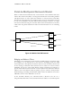
Point-to-Multipoint Network Model
When we talk about the PMP network, one should look at the Subscriber Unit (SU)
and the Base Station Unit (BSU) as an integrated transmission and switching medium
with physical ports or access points that interface to end user devices. Each Base
Station Unit or SU represents one such physical port or access point. Packets received
by a SU are transmitted to the Base Station Unit and emerge out from it as a single
data stream. Packets flowing into the Base Station Unit are broadcasted to the SUs,
which select only packets destined for their local networks based on a set of filtering
criteria.
Figure 2-2: Model of the PMP network
Bridging and Address Filters
Depending on the transmission mode selected, the PMP network can function either
as a "bridge" or as an "IP gateway" to the end user. In Bridging mode, the PMP
network provides a direct physical connection between a SU and its Base Station Unit
for the exchange of Ethernet frames between the two entities. To conserve wireless
bandwidth, the SU uses some simple filtering criteria in hardware and software to
prevent traffic destined for local network to be sent uplink. If the destination Ethernet
address is not in the hardware table, the packet is given to software, which provides
further filtering by matching the destination address with local addresses stored in its
ARP table. The size of the ARP table is set to 512.
In the downlink direction, the outbound traffic is filtered in the SU via a
"Programmable Hash Filter". If the destination Ethernet address of a downlink packet
BSU
port
SU
port
SU
port
SU
port
LAN traffic
LAN traffic
LAN traffic
LAN
traffic
PMP Network