
Specifications


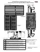

5C3B9@D9?> The RS-1 Solenoid release / initiat-
ing device card provides one supervised solenoid
output circuit. This circuit electrically energizes
the coil of a releasing agent control valve and is
equipped with "Trouble" and "Trip" L.E.D. indica-
tors for complete valve supervision and activation
monitoring. An on-board auxiliary alarm (release)
contact is supplied making remote signaling upon
solenoid activation easily implemented. This card
is also equipped with one Class B initiating device
circuit that is jumper selectable for either alarm or
supervisory field components. A meter read switch
is provided to activate alarm point location on the
circuit when used in systems employing the Protectowire Alarm Point Location Meter.
(5<51C59B3E9D3D9F1D9?>%@5B1D9?>
Trip - When the releasing output circuit is triggered by the appropriate pro-
grammed zone/s, the solenoid coil is energized opening the control valve allowing the extinguishing agent to be expelled.
The "Trip" indicator (red) will light showing that voltage has been supplied to the releasing circuit field terminals. Cross-
zoned operation is achieved through the use of the
ZV-91 (see option V) or by removing micro-
jumper MJ3 and applying activation signals to the
designated terminals of the Main Board MB-91A
or Expander Board EB-91A.
(5<51C59B3E9D*B?E2<5%@5B1D9?>
)8?BD- If a short circuit (less than 2.5 Ohms)
occurs across the solenoid output circuit the "SYS.
TRO." L.E.D. (yellow) on the Control Card flash-
es, the system trouble buzzer pulses, and the sole-
noid card "Trouble" L.E.D (yellow) lights steady.
Clear any short to restore to standby.
%@5>
- If an open in the field wiring to the sole-
noid coil occurs (greater than 1500 Ohms) the "SYS. TRO." L.E.D. flashes, the trouble buzzer pulses, and the solenoid card
"Trouble" L.E.D (yellow) lights steady. Clear the open to restore to standby.
)?<5>?949C3?>>53D
Prior to servicing the control panel the solenoid coil/s must be disconnected to prevent accidental
release of extinguishing agents. Simply toggle the "SOL. DISC." Switch down to the "OUT" position. A Solenoid trouble
condition will be indicated. Press "TRO. SIL." To silence the system. *)*#*%*%$)+($)*
$*")()*%(#%,"-()$+*%-*()+&&"/*%,
)%$$*)-*)%+"%$"/+)-$$%%*(#*%%)%$$*)
)"
~ 36 ~
%@D9?>LM)?<5>?94(5<51C5>9D91D9>745F93531B4()
>9D91D9>745F93539B3E9D?@5B1D9?> <1CC%><I
<1B=- A shorted detection or supervisory device will initiate the circuit to an alarm condition. Detection devices will cause
the system to function in the fire alarm mode of operation. The on card zone "Alarm" indicator (red) will light steady; the
"Sys. Alarm." indicator (red) on the Control Card CC-91A will light steady. The common alarm contacts on the MB-91A
will transfer, and the common alarm Notification Appliance Circuits will operate. Any auxiliary panel functions designed to
operate upon an alarm condition, will operate at this time.
)E@5BF9C?BI<1B=
- Supervisory devices will initiate supervisory alarm mode of operation. The on card zone "Alarm"
indicator (yellow) will light steady; the "System. Trouble / Sup." indicator (yellow) on the Control Card CC-91A will light
steady. The system trouble buzzer will sound steady and the common supervisory and common trouble contacts on the
MB-91A will transfer.
*B?E2<5
- An open in the Class B loop will initiate the circuit into a trouble condition. The on card zone "Trouble" indicator
(yellow) will light steady; the "Sys. Tro." Indicator (yellow) on the CC-91A will flash; the system trouble buzzer will pulse
.
READ
METER
SOLENOID
DISCONNNECT
SWITCH
SWITCH
DET.
ALARM
DET.
TROUBLE
TRIP
SOL.
SOL.
TROUBLE
RS-1