
Specifications


~ 34 ~
&&""%(#&&(%,)/)*#)%$"/
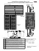
WATERFLOW #1
WATERFLOW #2
ELR-4.7K
0-95<4-9B9>7
%@D9?>LM-1D5B6<?G5D53D9?>1B40-
The zone card ZC-91AW provides two Class A or Class B alarm initiating device circuits for waterflow detection monitoring.
Both waterflow alarm circuits are equipped with alarm and trouble indicators for immediate off normal status identification.
The waterflow card must be programmed per jumper settings noted below and plugs into the Main Board MB-91A/M and/or
Expander Boards EB-91A/M printed circuit board card slots.
Operation:
Alarm - A shorted waterflow device will initiate the circuit into an alarm condition. Detection devices will cause the system to
function in the fire alarm mode of operation. The on-card zone “ALARM” (red) indicator will light steady; the “SYSTEM
ALARM” (red) indicator on the Control Card CC-91A will light steady. The common alarm contacts on the MB-91A will trans-
fer, and both Notification Appliance Circuits will operate.
Trouble
- An open in the detection loop will initiate the circuit into a trouble condition. The on-card zone “TROUBLE” (yel-
low) indicator will activate as well as the “SYSTEM TROUBLE/SUP” indicator on the control card CC-91A will flash; the sys-
tem trouble buzzer will pulse.
Terminations
on expander
board terminals
TE1 or TE2
0- E=@5B)5DD9>7C
0->4931D?BC
0-,1B91D9?>C
<53DB931<>9D91D9>75F9359B3E9D
Voltage Standby 22VDC
Current to Insure Alarm 13mA
Minimum Resistance to
Insure Alarm
<1.48K ohm
End of Line Device
(Class B only)
ELR-4.7K, 1/2 Watt, 5%
Supervisory Current 4.7mA
MJ1 & 2
Placed across JP1 & 2 terminals 1 & 2 when circuits are
employed as waterflow detection zones.
MJ7 & 8
Place jumper across JP7 & JP8 to make detection circuits
assigned for waterflow alarm
MJ9
Placed across JP9 terminals 1 & 2 for trouble indications to
remain active during alarm mode
MJ10 & 11
JP10 & JP11 must always be installed for circuits assigned for
waterflow alarm
ZC-91AW Standard system zone card: Provides (2) Class A/B detection circuits
ZI-91AW Intrinsic Waterflow zone card: Provides (2) Class B waterflow detection circuits compatible with Intrinsic Safety barriers.
ALARM Red Zone alarm indicator: Activates with respect to each zone in ALARM condition
TROUBLE Yellow Zone trouble indicator: Activates in respect to each zone in TROUBLE condition
Provides the circuitry
required to operate the Class
A/B waterflow initiating
devices. Designed with plug
in package for field repair
ease. This card plugs into the
Main or Expander board
modules