
Specifications


~ 30 ~
Provides the circuitry required
to operate the various Class A/B
initiating devices. Designed
with plug-in package for field
repair ease. This board plugs
into Main Control or Expander
board modules.
&&""%(#&&(%,)/)*#)%$"/
0?>51B4#?4E<50
?B5D53D9?>@@<931D9?>C
09C@<1I
&1>5<
0,1B91D9?>C
0?>DB?<)G9D385C
0>4931D?BC)D1>41B4*I@50?>51B4
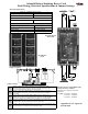
DESCRIPTION:
The zone card ZC-91A provides two Class A/B alarm initiating device circuits configured for alarm monitoring. Each zone is
individually equipped with alarm (red) and trouble (yellow) indicators for immediate status identification. This card plugs into
the second edge connector slot of the Main Board (MB-91A/M) and/or any Expander Board module (EB-91A/M)
Operation:
Alarm - A shorted detection circuit will initiate the panel into an alarm condition. The detection zone “ALARM” (red) indicator
will light steady and the “SYS. ALARM” (red) indicator on the Control Card (CC-91A) will activate. The common alarm con-
tacts on the MB-91A will transfer, and both general alarm Notification Appliance Circuits will operate.
Alarm Point Location
- In metered systems, once a zone is in alarm depress and hold down the respective zone switch (SW1 or
SW2) to display zone alarm point location of corresponding zone. Depressing switch will transfer alarm point location onto alarm
point location digital display (PWM-1000-2).
0 E=@5B)5DD9>7C
<53DB931<>9D91D9>75F9359B3E9D
Voltage Standby 22VDC
Current to Insure Alarm 13mA
Minimum Resistance to
Insure Alarm
<1.48K ohm
End of Line Device
(Class B only)
ELR-4.7K, 1/2 Watt, 5%
Supervisory Current 4.7mA
MJ1 & 2
Jumpers installed across terminal 1 & 2 on micro-header JP1 &
JP2 todesignate initiating circuits for detection zones.
MJ3 & 4
Installed when intrinsic safety barriers (Option H) for hazardous
locations are required
MJ5 thru 8
MJ5 & 6 are not installed
MJ7 & 8 are installed when circuits aassigned as detection zones
MJ9
Placed across JP9 terminals 1 & 2 for trouble indications to
remain active during alarm mode
MJ10 & 11 Jumpers are not required for detection zone usage.
ZC-91A Standard system zone card: Provides (2) Class A/B detection circuits
ZC-91AM Metered system zone card: Provides (2) Class A/B detection circuits compatible with alarm point location meter.
ZI-91A Intrinsic system zone card: Provides (2) Class B detection circuits compatible with intrinsic safety barriers
ZI-91AM
Intrinsic Metered system zone card: Provides (2) Class B detection circuits compatible with intrinsic safety barriers & alarm
point location meter
ALARM Red Zone alarm indicator: Activates with respect to each zone in ALARM condition
TROUBLE Yellow Zone trouble indicator: Activates in respect to each zone in TROUBLE condition
Meter Switch
Zone 1
Meter read switch Zone 1: Press and hold to read distance (ft/m) to alarm actuation point of Protectowire zone in alarm:
See Option A - Protectowire alarm point location meter
Meter Switch
Zone 2
Meter read switch Zone 2: Press and hold to read distance (ft/m) to alarm actuation point of Protectowire zone in alarm:
See Option A - Protectowire alarm point location meter