
User's Manual


044-05251 Rev C 2-1
Chapter 2
Controls, Indicators and Connectors
Introduction
This chapter contains descriptions of the controls, indicators and connectors for the WRH.
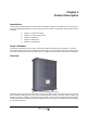
Front Cover Indicators
Figure 2-1 External Indicators
Two LEDs, shown in Figure 2-1, are located on the front cover to prov
ide easy identification of a fault in the
system. The amber operation LED lights up approximately 15 seconds after the main power is switched on.
When the LED is steady, the WRH is ready for operation. The red alarm LED indicates a system error alarm
when flashing and a critical alarm when steady.
Cabinet Indicators
Figure 2-2 Cabinet Internal Indicators
Red
Amber
MS
DPX
ANT
TEST
DC
-30 dB
-20 dB
MS
DPX
ANT
TEST
DC
-30 dB
-20 dB
ALLGON IN NOVAT ION
SWEDEN M105 R6
1
PARKING
FOR W5
W5
8
P27
W6B 10
1
P33
ALARM
P23
LNA
UP-LINK
P32
MODE M
A
U
X
1
P28
DOOR
5
9
6
1
1
16
1
1
M
-
>
S
P11
P34
8
9
15
P26
15 16
S
-
>
M
1
2
3
89
P
3
6
5
X0A
X0B
2
V2
1
16
P12 P13
1
1
1
16
16
16
P4
P5
P6
c
b
a
c
b
a
c
b
a
c
b
a
1P232
1
b
a
1
16P3
16
1
16
P14
1
V1
1
1
1
1
1
4
6
1
15
6
9
15
2
16
1
2
4
5
8
5
P35
P21
PSU
6
10
P31
PC
P29
P24
P25
GND
7
6V6
LNA
DOWN-LINK
LED
P22
1
2
POWER SUPPLY UNIT
CU
ALI
or
RCI
SV
OPER
FAULT
POWER
10V
ALARM
POWER
BOOT
FAULT
OPER
WLI / R2R
DATA