
Owner's Manual


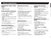


Table Of Contents
- Owners Manual
- Reset (Button #2)
- Bluetooth PIN (0000)
- Parking Brake Interlock
- First-Time Startup
- Table of Contents
- Parts & Controls
- Operation
- System Settings
- Audio Adjustments
- Theme Menu
- Favorite Menu
- Connection / Installation
- Troubleshooting
- Messages
- Specs
- Warranty

Connection
•
The
black
cable
is ground. When installing this unit
or power
amp
(sold
separately),
make
sure to connect
the ground wire first. Ensure that the ground
wire
is
properly
connected to
metal
parts of the car's body.
The
ground wire of the power
amp
and the one of this
unit or any other device must be connected to
the
car
separately
with
different screws.
If
the screw for the
ground
wire
loosens
or
falls
out, it
could result
in fire
generation of smoke or malfunction.
Ground
wire
POWER
AMP
~,,~
,
/;;
Ll-
*1~t~
(:)
(:)
\-
Other
devices
Metal
parts
of
car's
body
(Another
electronic
device
in
the
car)
*
1 Non supplied for this
unit
• When replacing
the fuse, be sure to
only
use a fuse of
the rating prescribed
on
this product.
•
This
product
cannot
be
insta
lled in a
ve
hic
le
wi
thout
ACC
(
accessory)
position
on
the
igniti
on
switch.
ACC
position
No
ACC
position
•
To
avoid
short
-circ
uiting
, cover the
dis
connec
ted lead w ith
insulatin
g tape.
It
is es pecially
important
to insulate all
unus
ed
speaker leads.
which
if left uncovered
rnay
cause a
short
circuit.
•
F
or
connect
ing a
power
amp
or o
ther
devices to
this
product.
1·efer
·
to the
manual
for
the
produ
ct
to
be
connect
ed.
Notice
for
the
blue/white
lead
• W hen
the ig nition
sw
i
tch
is
turn
ed on
(ACC ON).
a
control
signal is
output
through
the
blue/white
lead.
Connect
to an
external po
wer
amp
's
sy
stem remote
contr
ol
terrn~nal,
the
auto-antenna
relay
control
terminal.
or
the
antenna booster
p
ower
co
ntrol
terminal
(
ma
x.
300
rnA
12
V DC
).
The
control
signal is o
utput
thro
ugh the blue/
wh
ite lead. even if
the
audio
source
1s
switched
off.
This
product
•-----,
CD
®CD
CD
Microphone
3
rn
(9ft.
10-
1/8
in.)
@
This
product
G)
Antenna
jack
®
Wir
ed
remo
te in put
®®
@®
Hard-wired remote control
adapter
ca
n be
co
nnect
ed
(sold
separately).
(
[J
Pow
er·
supply
(0 Fuse
(1
0
A)
(j)
Front ou
tput
(]_
)
Rear
output
or
subwoofer
output
Power
cord
-"~--
®
--
(4)
•""'---
®
·---
®
·---
cv
'----
®
CD
To
power supply
(
~
)
Po
wer
cord
Q)
Ye
ll
ow
To
term
1nal
supplied
with
power regardless of
ignition
switch
pOSiti
on.
(!
1
Red
To
electric
t
ermina
l
control
l
ed
by i
gnit
ion switch
(12
V
DC)
ON
/O
FF.
(0
Orange/white
To
l
ighting
switch
terminal.
(§
)
Black
(ground)
To
veh icle (metal) body.
(!.)
Violet/white
Of
the
tw
o lead
wir·es
co
nnected to the back
lamp,
connect
the one in which
the
voltage
changes
whe
n the
gear
s
hift
is in
the
REVERSE
(
R)
position.
Th
is
connection
enables
the
unit
to sense
whether
the
car
is moving forwards or
backwards.
®
Blue/ white
Connect
to sy
stem
control
te
rminal
of the power
amp
(rnax.
300
mA
12
V
DC).
(
~
)
Light green
Used to detect the
ON/
OFF
status
of the
par·king
brake. This
27