
Datasheet


PNOZmulti products
Speed monitors
PNOZ ms2p HTL
Pilz GmbH & Co. KG, Felix-Wankel-Straße 2, 73760 Ostfildern, Germany
Telephone: +49 711 3409-0, Telefax: +49 711 3409-133, E-Mail: info@pilz.com
2015-11
298
X12
X22
Speed monitor
24 V DC
0 V
2
4
5
7
8
A
/A
B
/B
24 V
0 V
Incremental
encoder
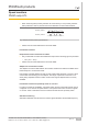
Fig.: Connection to incremental encoder type 24 V-HTL
Connect incremental encoder to the speed monitor via an adapter
} The adapter is connected between the incremental encoder and the drive. The output
on the adapter is connected to the female RJ45 connector on the speed monitor.
} The adapter can also be used without connecting to a drive.
} The signals relevant for the speed monitor are utilised in parallel by the adapter. The in-
formation stated under "Connect incremental encoder signals to the speed monitor" and
in the adapter operating manual must be observed when connecting the supply voltage.
} Supply voltage (12 V – 30 V) to incremental encoder only.
} HTL signals may not be fitted with a terminating resistor.
Incremental
encoder
A
/A
B
/B
X12
X22
Speed monitor
Drive
Adapter
24 V
0 V
24 V DC
0 V
1 8
Fig.: Connection via adapter and drive