
Datasheet


Relays for functional safety
Safety relays PNOZsigma
PNOZ s50
Pilz GmbH & Co. KG, Felix-Wankel-Straße 2, 73760 Ostfildern, Germany
Telephone: +49 711 3409-0, Telefax: +49 711 3409-133, E-Mail: info@pilz.com
2016-09
931
Option two:
1. Select Reboot in menu level 3.
2. Select Yes and press the rotary knob.
The device is restarted and the configuration is adopted.
Examples
Overview
This chapter provides information on how to connect the PNOZs50 to a safety control sys-
tem. The connections illustrated are independent of any specific control system.
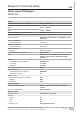
Mechanical holding brake
Properties
PNOZ s50
} Safe activation of two independent mechanical holding brakes
} Ventilation and application times are monitored
} Fast and slow shutdown of both brakes
} Feedback loop for brake B1 is monitored via input Y1
} Feedback loop for brake B2 is monitored via input Y2
} Fuses
– F1: 24 V DC, 4 A, characteristic B/C
– F2: 24 V DC, 10 A, characteristic B/C
Safety control system
} Inputs:
– Fault signal O3
– State of brakes O4, O5 (applied, ventilated) is monitored
} Outputs
– Activation of fast and slow shutdown of brake
Brake
} Micro switch S1 to signal the state of brake B1
} Micro switch S2 to signal the state of brake B2