
Datasheet


Relays for functional safety
Safety relays PNOZsigma
PNOZ s7.2
Pilz GmbH & Co. KG, Felix-Wankel-Straße 2, 73760 Ostfildern, Germany
Telephone: +49 711 3409-0, Telefax: +49 711 3409-133, E-Mail: info@pilz.com
2016-09
731
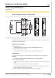
Block diagram/terminal configuration
Fig.: Centre: Front view with cover, right: Front view without cover
*Safe separation from non-marked area in accordance with EN 60947-1, 6 kV, basic insula-
tion between all safety contacts.
Function description
with PNOZsigma s7.1:
} Dual-channel operation and supply voltage via PNOZsigma connector
with PNOZsigma expander modules:
} Dual-channel operation and supply voltage via PNOZsigma connector
Installation
Connect contact expansion module PNOZ s7.2 to PNOZsigma contact expansion
modules
} Connect the contact expansion modules using the connector supplied.
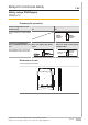
Control cabinet installation
} The safety relay should be installed in a control cabinet with a protection type of at least
IP54.
} Use the notch on the rear of the unit to attach it to a DIN rail.
} Ensure the unit is mounted securely on a vertical DIN rail (35 mm) by using a fixing ele-
ment (e.g. retaining bracket or an end angle).
Push the unit upwards or downwards before lifting it from the DIN rail.