
Datasheet


Relays for functional safety
Safety relays PNOZsigma
PNOZ s7
Pilz GmbH & Co. KG, Felix-Wankel-Straße 2, 73760 Ostfildern, Germany
Telephone: +49 711 3409-0, Telefax: +49 711 3409-133, E-Mail: info@pilz.com
2016-09
706
Wiring
Please note:
} Information given in the "Technical details [ 708]" must be followed.
} Outputs 13-14, 23-24, 33-34, 43-44 are safety contacts; outputs 51 -52 are auxiliary
contacts (e.g. for display).
} Auxiliary contact 51-52 shouldnot be used for safety circuits!
} To prevent contact welding, a fuse should be connected before the output contacts (see
Technical details [ 708]).
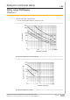
} Calculation of the max. cable length l
max
in the input circuit:
R
lmax
R
l
/ km
I
max
=
R
lmax
= max. overall cable resistance (see Technical details [ 708])
R
l
/km = cable resistance/km
} Use copper wire that can withstand 60/75°C.
} Sufficient fuse protection must be provided on all output contacts with capacitive and in-
ductive loads.
} Ensure the wiring and EMC requirements of IEC 60204-1 are met.
} The power supply must comply with the regulations for extra low voltages with protect-
ive electrical separation (SELV, PELV) in accordance with VDE 0100, Part 410.
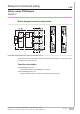
Preparing for operation
Supply voltage AC DC
A1
A2
24 V DC
0 V
PNOZsigma
expansion
module
Input circuit Single-channel Dual-channel
Base unit:
Safety relay PNOZX
A1
A2
24 V DC
0 V
PNOZsigma
expansion
module
Base unit:
Safety relay PNOZelog
Driven via semiconductor outputs
(24 VDC)
A1
A20 V
O1
L-
PNOZsigma
expansion
module