
Datasheet


Relays for functional safety
Safety relays PNOZ X
PNOZ X3.10P
Pilz GmbH & Co. KG, Felix-Wankel-Straße 2, 73760 Ostfildern, Germany
Telephone: +49 711 3409-0, Telefax: +49 711 3409-133, E-Mail: info@pilz.com
2016-09
150
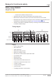
Installation
} The unit should be installed in a control cabinet with a protection type of at least IP54.
} Use the notch on the rear of the unit to attach it to a DIN rail.
} Ensure the unit is mounted securely on a vertical DIN rail (35 mm) by using a fixing ele-
ment (e.g. retaining bracket or an end angle).
Wiring
Please note:
} Information given in the "Technical details [ 154]" must be followed.
} Outputs 13-14, 23-24, 33-34 are safety contacts; output 41-42 is an auxiliary contact
(e.g. for display).
} Auxiliary contact 41-42 shouldnot be used for safety circuits!
} Do not connect undesignated terminals.
} Delivery status of units with screw terminals: Link between S11-S12 (dual-channel input
circuit) and link between S15-S16 (safety gate with start-up test)
} To prevent contact welding, a fuse should be connected before the output contacts (see
Technical details [ 154]).
} Calculation of the max. cable length l
max
in the input circuit:
R
lmax
R
l
/ km
I
max
=
R
lmax
= max. overall cable resistance (see Technical details [ 154])
R
l
/km = cable resistance/km
} Use copper wire that can withstand 60/75°C.
} Do not switch low currents using contacts that have been used previously with high cur-
rents.
} Sufficient fuse protection must be provided on all output contacts with capacitive and in-
ductive loads.
} When connecting magnetically operated, reed proximity switches, ensure that the max.
peak inrush current (on the input circuit) does not overload the proximity switch.
} The power supply must comply with the regulations for extra low voltages with protect-
ive electrical separation (SELV, PELV) in accordance with VDE 0100, Part 410.
} Ensure the wiring and EMC requirements of IEC 60204-1 are met.
Important for detection of shorts across contacts:
As this function for detecting shorts across contacts is not failsafe, it is tested by Pilz during
the final control check. If there is a danger of exceeding the cable length, we recommend
the following test once the unit is installed:
1. Unit ready for operation (output contacts closed)
2. Short circuit the test terminals S22, S32 for detecting shorts across the inputs.