
Datasheet


For further information and full technical data, visit phoenixcontact.net/products
Technical data
1
) Technical data
1
)
Dimensions Width Length Height Width Length Height
[mm] 5.2 93.5 51.5 (NS 35/7,5) 5.2 93.5 51.5 (NS 35/7,5)
Max. electrical data I
max.
[A] U
max.
[V] max. Ø [mm²] AWG (UL) I
max.
[A] U
max.
[V] max. Ø [mm²] AWG (UL)
30
2
) 400 0.2 - 4 26-12 30 400 0.2 - 4 26-12
Max. bridge current [A] 24 (FBS) / 17.5 (FBSR) 24 (FBS) / 17.5 (FBSR)
Rated data IEC UL / CUL CSA Ex IEC UL / CUL CSA Ex
Rated voltage [V] 400 300 - - 400 300 - -
Nominal current / cross section [A] / [mm²] 24 / 4 20 - - 24 / 4 20 - -
Rated cross section [mm²] 4 4
Cross section range AWG 24 - 12 - - - 24 - 12 - - -
Connection capacity solid stranded Ferrule
without/with plastic sleeve
solid stranded Ferrule
without/with plastic sleeve
1 conductor [mm²] 0.2 - 4 0.2 - 4 0.25 - 2.5 0.25 - 2.5 0.2 - 4 0.2 - 4 0.25 - 2.5 0.25 - 2.5
2 conductors (of the same type) [mm²] 0.2 - 1.5 0.2 - 1.5 0.25 - 0.75 - 0.2 - 1.5 0.2 - 1.5 0.25 - 0.75 -
Ordering data Ordering data
Description Color Type Order No.
Pcs. /
Pkt.
Type Order No.
Pcs. /
Pkt.
Terminal block gray UTI 2,5-PE/L/L ① 3076029 50 UTI 2,5-PE/L/N ① 3076030 50
Accessories
1
) Accessories
1
)
Cover, width 2.2 mm gray D-UTI/3 3076036 50 D-UTI/3 3076036 50
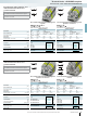
Terminal blocks - CLIPLINE complete
2.5 mm UT... screw connection terminal blocks
4 (4) mm², 30 A, three-level terminal block,
2 x L phase conductor, 1 x PE
4 (4) mm², 30 A, three-level terminal block,
1 x L phase conductor, 1 x N conductor, 1 x PE
①①
Installation terminal blocks
Notes:
1
) For additional accessories and technical data, see page 30.
2
) 3-pos. termination block.
Assembly instruction:
In order to securely fix the neutral busbar in place, support
brackets must be placed at the beginning and end of each terminal
strip as well as every 20cm on longer terminal strips.
The corresponding support brackets can be found at
phoenixcontact.net/products
Technical data
1
) Technical data
1
)
Dimensions Width Length Height Width Length Height
[mm] 5.2 93.5 51.5 (NS 35/7,5) 5.2 93.5 51.5 (NS 35/7,5)
Max. electrical data I
max.
[A] U
max.
[V] max. Ø [mm²] AWG (UL) I
max.
[A] U
max.
[V] max. Ø [mm²] AWG (UL)
30
2
) 400 0.2 - 4 26-12 30
2
) 400 0.2 - 4 26-12
Max. bridge current [A] 24 (FBS) / 17.5 (FBSR) 24 (FBS) / 17.5 (FBSR)
Rated data IEC UL / CUL CSA Ex IEC UL / CUL CSA Ex
Rated voltage [V] 400 300 300 - 400 300 300 -
Nominal current / cross section [A] / [mm²] 24 / 4 20 / - 20 / - - 24 / 4 20 / - 20 -
Rated cross section [mm²] 4 4
Cross section range AWG 24 - 12 - - - 24 - 12 - - -
Connection capacity solid stranded Ferrule
without/with plastic sleeve
solid stranded Ferrule
without/with plastic sleeve
1 conductor [mm²] 0.2 - 4 0.2 - 4 0.25 - 2.5 0.25 - 2.5 0.2 - 4 0.2 - 4 0.25 - 2.5 0.25 - 2.5
2 conductors (of the same type) [mm²] 0.2 - 1.5 0.2 - 1.5 0.25 - 0.75 - 0.2 - 1.5 0.2 - 1.5 0.25 - 0.75 -
Ordering data Ordering data
Description Color Type Order No.
Pcs. /
Pkt.
Type Order No.
Pcs. /
Pkt.
Terminal block gray UTI 2,5-L/L ① 3076031 50 UTI 2,5-L ① 3076034 50
upper level blue gray UTI 2,5-L/N ① 3076035 50
Accessories
1
) Accessories
1
)
Cover, width 2.2 mm gray D-UTI/3 3076036 50 D-UTI/3 3076036 50
37
PHOENIX CONTACT
4 (4) mm², 30 A, three-level terminal block,
2 x L phase conductor
4 (4) mm², 30 A, three-level terminal block,
1 x L phase conductor
①①
Installation terminal blocks
Notes:
1
) For additional accessories and technical data, see page 30.
2
) 3-pos. termination block.
Assembly instruction:
In order to securely fix the neutral busbar in place, support
brackets must be placed at the beginning and end of each terminal
strip as well as every 20cm on longer terminal strips.
The corresponding support brackets can be found at
phoenixcontact.net/products