
Datasheet


For further information and full technical data, visit phoenixcontact.net/products
607PHOENIX CONTACT
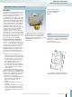
In practice, tensile forces can affect the
terminal point during wiring or operation.
Therefore, terminal blocks must be wired
correctly to offer a high degree of
mechanical safety. To test the tensile load
capacity of a terminal point, the terminal
point must withstand a given tensile force
based on the cross section for over 60
seconds. This test is performed after the
bending test. Performing these two tests
directly one after the other intensifies the
requirements. The tensile force exerts stress
on the conductor at the terminal point. The
conductor must be held without causing
damage. The test results for terminal blocks
from Phoenix Contact are up to 150% above
the required minimum values.
IEC 60947-7-1/-2
Conductor pull-out test
Absorption of tensile force on a
10 mm
2
spring-cage terminal block
Conductor pull-out forces according to
IEC 60999/EN 60999/VDE 0609-1, Table
III (up to 35 mm
2
)
Conductor cross section Tensile force
[mm
2
] AWG/kcmil [N]
0.2
–
24
22
10
20
0.5
0.75
20
18
15
30
1.0
1.5
–
16
35
40
2.5
4.0
14
12
50
60
6.0
10
10
8
80
90
16
25
6
4
100
135
–
35
3
2
156
190
–
50
1
0
236
236
70
95
00
000
285
351
–
120
0000
250
427
427
150
185
300
350
427
503
–
240
400
500
503
578
300
600 578
Besides the reliable contacting of the
conductor, the terminal block itself must be
able to withstand forces without coming
loose from its support. Furthermore, no
unacceptable damage may occur. To test
whether the fit is tight, a terminal block is
mounted on a standard DIN rail according to
the manufacturer's information. Then steel
rods with a length of 150 mm are clamped
into the terminal points. Tensile and
pressure forces based on the cross section
are exerted on the terminal points and the
latching of the terminal block with a lever
distance of 100 mm. The terminal block
must not come loose or break off the rail.
The structural design of the terminal blocks
from Phoenix Contact ensures a reliable
tight fit on different DIN rail systems.
IEC 60947-7-1/-2
Tight fit of terminal block
Cross section Cross section Force Diameter of the steel rod
[mm
2
] AWG [N] [mm]
0.75 18 1 1.0
1 1 1.0
1.5 16 1 1.0
2.5 14 1 1.0
4121 1.0
6 10 5 2.8
10 8 5 2.8
35 2 10 5.7
50 0 10 5.7
240 500 kcmil 20 20.5
Rail or support
100 mm 100 mm
Force Force
Technical information
Quality tests