
Datasheet


MINI MCR-SL-PT100-UI-200
102478_en_02 10
PHOENIX CONTACT GmbH & Co. KG • 32823 Blomberg • Germany • Phone: +49-(0) 5235-3-00
PHOENIX CONTACT • P.O.Box 4100 • Harrisburg • PA 17111-0100 • USA • Phone: +717-944-1300
www.phoenixcontact.com
8Diagnostics LED
The LED which is visible on the front displays the following
faults:
– LED flashing: Measuring range span less than 50 K
– LED ON: Open circuit on the sensor side
– LED ON: Short circuit on the sensor side
– LED ON: Measuring range overrange
– LED ON: Measuring range underrange
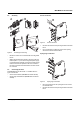
9 Connection/Application example
2-wire connection method
– For short distances (< 10 m)
– Cable resistances RL1 and RL2 are incorporated in the
measurement result directly and falsify the result accord-
ingly.
Figure 6 2-wire connection
3-wire connection method
– For long distances between PT100 sensor and MINI an-
alog module
– The value of all cable resistances must be exactly the
same (RL1 = RL2 = RL3) in order to balance out the sen-
sor cable resistances.
Figure 7 3-wire connection
4-wire connection method
– For longer distances between PT100 sensor and MINI
analog module and differing cable resistances (RL1 ≠
RL2 ≠ RL3 ≠ RL4).
Figure 8 4-wire connection
IN
4
2
3
1
IN
4
2
3
1
IN
4
2
3
1