
User's Manual


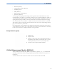


Table Of Contents
- IntelliVue Patient Monitor
- 1 Introduction 13
- 2 Alarms 49
- 3 Patient Alarms and INOPs 65
- 4 Managing Patients 95
- 5 ECG, Arrhythmia, ST and QT Monitoring 111
- 6 Monitoring Pulse Rate 155
- 7 Monitoring Respiration Rate (Resp) 159
- 8 Monitoring SpO2 165
- 9 Monitoring NBP 173
- 10 Monitoring Temperature 181
- 11 Monitoring Invasive Pressure 183
- 12 Monitoring Cardiac Output 195
- 13 Monitoring Carbon Dioxide 213
- 14 Monitoring Airway Flow, Volume and Pressure 225
- 15 Monitoring tcGas 233
- 16 Monitoring Intravascular Oxygen Saturation 241
- 17 Monitoring EEG 249
- 18 Monitoring BIS 257
- 19 Assigning a Telemetry Device and a Monitor to One Patient 265
- 20 Trends 271
- 21 Calculations 283
- 22 High Resolution Trend Waves 289
- 23 Event Surveillance 291
- 24 ProtocolWatch 309
- 25 Recording 317
- 26 Printing Patient Reports 325
- 27 Using the Drug Calculator 337
- 28 IntelliBridge EC10 Module 343
- 29 VueLink Modules 347
- 30 Using Timers 351
- 31 Respiratory Loops 355
- 32 Laboratory Data 359
- 33 Care and Cleaning 361
- 34 Maintenance and Troubleshooting 365
- 35 Accessories 369
- 36 Specifications 387
- 37 Default Settings Appendix 429
- Index 449
- Introduction
- Introducing the Monitor
- Devices for Acquiring Measurements
- Operating and Navigating
- Operating Modes
- Understanding Screens
- Connecting Additional Displays to the Monitor
- Using the XDS Remote Display
- Using the Visitor Screen
- Understanding Profiles
- Understanding Settings
- Changing Wave Speeds
- Freezing Waves
- Using Labels
- Entering Measurements Manually
- Changing Monitor Settings
- Checking Your Monitor Revision
- Getting Started
- Disconnecting from Power
- Networked Monitoring
- Using the Integrated PC
- Using the X2 or MP5 with a Host Monitor
- Alarms
- Patient Alarms and INOPs
- Patient Alarm Messages
- Technical Alarm Messages (INOPs)
- Monitor INOPs
- Battery INOPs
- MMS, MMS Extensions and FMS INOPs
- Display INOPs
- ECG, Arrhythmia, QT and ST INOPs
- Pulse INOPs
- Resp INOPs
- NBP INOPs
- Temperature INOPs
- SpO2 INOPs
- Pressure INOPs
- CO2 INOPs
- SO2 INOPs
- C.O. INOPs
- tcGas INOPs
- EEG INOPs
- BIS INOPs
- Spirometry INOPs
- VueLink INOPs
- IntelliBridge INOPs
- Telemetry INOPs
- ProtocolWatch INOPs
- Calculated Values INOPs
- Cableless Measurement Device INOPs
- Managing Patients
- Admitting a Patient
- Quick Admitting a Patient
- Editing Patient Information
- Discharging a Patient
- Transferring Patients
- Data Upload from an MMS
- Care Groups
- ECG, Arrhythmia, ST and QT Monitoring
- Skin Preparation for Electrode Placement
- Connecting ECG Cables
- Selecting the Primary and Secondary ECG Leads
- Checking Paced Status
- Understanding the ECG Display
- Monitoring Paced Patients
- Changing the Size of the ECG Wave
- Changing the Volume of the QRS Tone
- Changing the ECG Filter Settings
- Selecting Positions of Va and Vb Chest Leads (for 6-lead placement)
- Choosing EASI or Standard Lead Placement
- About ECG Leads
- ECG Lead Fallback
- ECG Lead Placements
- Capture 12-Lead
- EASI ECG Lead Placement
- ECG and Arrhythmia Alarm Overview
- Using ECG Alarms
- ECG Safety Information
- About Arrhythmia Monitoring
- Switching Arrhythmia Analysis On and Off
- Choosing an ECG Lead for Arrhythmia Monitoring
- Understanding the Arrhythmia Display
- Arrhythmia Relearning
- Arrhythmia Alarms
- About ST Monitoring
- Switching ST On and Off
- Understanding the ST Display
- Updating ST Baseline Snippets
- Recording ST Segments
- About the ST Measurement Points
- ST Alarms
- Viewing ST Maps
- About QT/QTc Interval Monitoring
- QT Alarms
- Switching QT Monitoring On and Off
- Monitoring Pulse Rate
- Monitoring Respiration Rate (Resp)
- Monitoring SpO2
- SpO2 Sensors
- Applying the Sensor
- Connecting SpO2 Cables
- Measuring SpO2
- SpO2 Signal Quality Indicator (Fast SpO2 only)
- Assessing a Suspicious SpO2 Reading
- Changing the Averaging Time
- Understanding SpO2 Alarms
- Pleth Wave
- Perfusion Numeric
- Perfusion Change Indicator
- Setting SpO2/Pleth as Pulse Source
- Setting Up Tone Modulation
- Setting the QRS Volume
- Calculating SpO2 Difference
- Monitoring NBP
- Introducing the Oscillometric NBP Measurement
- Preparing to Measure NBP
- Starting and Stopping Measurements
- Enabling Automatic Mode and Setting Repetition Time
- Enabling Sequence Mode and Setting Up The Sequence
- Choosing the NBP Alarm Source
- Switching Pulse from NBP On/Off
- Assisting Venous Puncture
- Calibrating NBP
- Monitoring Temperature
- Monitoring Invasive Pressure
- Setting up the Pressure Measurement
- Zeroing the Pressure Transducer
- Adjusting the Calibration Factor
- Displaying a Mean Pressure Value Only
- Changing the Pressure Wave Scale
- Optimizing the Waveform
- Using the Wave Cursor
- Non-Physiological Artifact Suppression
- Choosing the Pressure Alarm Source
- Calibrating Reusable Transducer CPJ840J6
- Calculating Cerebral Perfusion Pressure
- Calculating Pulse Pressure Variation
- Measuring Pulmonary Artery Wedge Pressure
- Editing the Wedge
- Identifying the Pressure Analog Output Connector
- Monitoring Cardiac Output
- Hemodynamic Parameters
- Using the C.O. Procedure Window
- Accessing the Setup C.O. and Setup CCO Menus
- Entering the HemoCalc Window
- Measuring C. O. Using the PiCCO Method
- Measuring C.O. Using the Right Heart Thermodilution Method
- Documenting C.O. Measurements
- C.O. Injectate Guidelines
- C.O./CCO Curve Alert Messages
- C.O./CCO Prompt Messages
- C.O./CCO Warning Messages
- C.O./CCO Safety Information
- Monitoring Carbon Dioxide
- Monitoring Airway Flow, Volume and Pressure
- Attaching the Flow Sensor
- Zero Calibration
- Automatic Purging
- Manual Purging
- Gas Compensation
- Setting up Spirometry
- Monitoring tcGas
- Monitoring Intravascular Oxygen Saturation
- Monitoring EEG
- Monitoring BIS
- Assigning a Telemetry Device and a Monitor to One Patient
- Trends
- Calculations
- High Resolution Trend Waves
- Event Surveillance
- Levels of Event Surveillance
- Event Groups
- Event Episodes
- Events Pop-Up Keys
- Event Triggers
- If You Use Alarm Limits As Event Triggers
- If You Set User-defined Threshold Triggers
- If You Set "On Measurement" Triggers
- If You Set Use-defined Deviation Triggers
- Event Retriggering
- Event Notification
- Setting Triggers for NER and Basic Event Surveillance
- Setting Triggers and Notification for Advanced Event Surveillance
- Triggering Events Manually
- Running a Car Seat Assessment Record
- The Events Database
- Viewing Events
- Annotating Events
- Documenting Events
- ProtocolWatch
- Recording
- Printing Patient Reports
- Starting Report Printouts
- Stopping Reports Printouts
- Setting Up Reports
- Setting Up Individual Print Jobs
- Checking Printer Settings
- Printing a Test Report
- Switching Printers On Or Off for Reports
- Dashed Lines on Reports
- Unavailable Printer: Re-routing Reports
- Checking Report Status and Printing Manually
- Printer Status Messages
- Sample Report Printouts
- Using the Drug Calculator
- IntelliBridge EC10 Module
- VueLink Modules
- Using Timers
- Respiratory Loops
- Laboratory Data
- Care and Cleaning
- Maintenance and Troubleshooting
- Accessories
- ECG/Resp Accessories
- NBP Accessories
- Adult/Pediatric Reusable Comfort Cuffs
- Adult/Pediatric Reusable Comfort Cuff Kits
- Adult/Pediatric Reusable EasyCare Cuffs
- Adult/Pediatric Single Patient Cuffs
- Adult/Pediatric Single Patient, Soft Cuffs
- Neonatal/Infant Single Patient Cuffs
- Neonatal/Infant Single Patient, Soft Cuffs
- Neonatal/Infant Cuff Kits
- Invasive Pressure Accessories
- SpO2 Accessories
- Temperature Accessories
- Cardiac Output (C.O.) Accessories
- Mainstream CO2 Accessories
- Sidestream CO2 Accessories
- Mainstream CO2 Accessories (for M3016A)
- Microstream CO2 Accessories
- Spirometry Accessories
- tcGas Accessories
- EEG Accessories
- BIS Accessories
- SO2 Accessories for M1021A
- SO2 Accessories for M1011A
- Recorder Accessories
- Battery Accessories
- Specifications
- Intended Use
- Manufacturer's Information
- Symbols
- Installation Safety Information
- Monitor Mounting Precautions
- Altitude Setting
- Monitor Safety Specifications
- EMC And Radio Regulatory Compliance
- Physical Specifications
- Environmental Specifications
- Performance Specifications
- Interface Specifications
- Measurement Specifications
- Safety and Performance Tests
- Default Settings Appendix
- Country-Specific Default Settings
- Alarm and Measurement Default Settings
- Alarm Default Settings
- ECG, Arrhythmia, ST and QT Default Settings
- Pulse Default Settings
- Respiration Default Settings
- SpO2 Default Settings
- NBP Default Settings
- Temperature Default Settings
- Invasive Pressure Default Settings
- Cardiac Output Default Settings
- CO2 Default Settings
- Spirometry Default Settings
- tcGas Default Settings
- Intravascular Oxygen Saturation
- SvO2 Default Settings
- ScvO2 Default Settings
- EEG Default Settings
- BIS Default Settings
- VueLink Default Settings

1 Introduction
19
The X2 has the added capability to operate as a stand-alone monitor, and can be powered by a
rechargeable battery. This makes it particularly suited to transport situations. When the X2 is
disconnected from the original host monitor, it continues to monitor the patient as a stand-alone
monitor running on battery power, eliminating the need for a separate transport monitor. When the
X2 is connected to a new host monitor, it resumes its role as MMS, ensuring fully continuous
monitoring. For details of using the X2 as a stand-alone monitor, refer to the IntelliVue X2 Instructions
for Use.
When connected to a host monitor (
Companion Mode is indicated), the X2 takes power from the
host, including that required for battery charging. The X2 can also be powered by AC mains when not
connected to a host monitor using the optionally available external power supply (M8023A). See the
IntelliVue X2 Instructions for Use for details.
X2 Overview
1 On/Standby switch
2 Power and battery indicators (see “X2
Controls and Indicators” on page 20)
3 3.5-inch TFT LCD touchscreen QVGA
display
4 Alarm lamps (see “X2 Controls and
Indicators” on page 20)
5 Battery eject button
6 Hard keys (see “X2 Controls and
Indicators” on page 20)
7 Measurement connectors (see “X2 Patient
Connectors, Right Side” on page 21)
8 Battery compartment