
ptmxmkhojfubayxr8nbt


3
www.rohlhome.com
Consult your local ROHL showroom for additional information and specifications. For complete warranty details and a list of showrooms, go to www.rohlhome.com.
INSTALLATION INSTRUCTIONS
SECTION 4
Non Return Valves. See figure 5.
To examine the non return valves, it
will be necessary to remove the
shower body from the installation
by following the procedure in
section 3. BEFORE ATTEMPTING TO
REMOVE THE SHOWER BODY
ENSURE THAT BOTH HOT AND COLD
SUPPLIES ARE ISOLATED.
The thermostatic shower is supplied
with non-return valves in the inlet
unions to prevent cross
contamination of the supplies. Du
ring storage the non-return valve
seals can become “stuck” and in conditions of low flow there is not
enough water pressure to initially open them. They can easily be
opened manually by pushing on the centre with a finger to free the
seals.
In conditions of extremely low flow the non-return valves can be
removed to reduce restrictions by breaking them out using a flat
bladed screwdriver and pointed n
ose pliers. Take care not to
damage the sealing surface on the inlet unions. This should only be
carried out where both supplies come from a common source installed
in accordance with the local plumbing codes.
SECTION 5
Shut off Valve not opening. See figure 6.
Before attempting to
remove the shut off valve
ensure that both hot and
cold supplies are isolated.
Take extreme care not to
damage any of the finish
ed
parts by protecting
surfaces of tools with
masking/insulating tape.
Undo and remove lever
screw. Pull lever/crosshead
assembly from spline of
1/4 turn ceramic valve. Undo and remove hood. Using a 17mm
spanner or socket, undo 1/4 turn ceramic valve. If the shower has
been used, as soon as the seal on the valve is broken water will flow
from around the valve and the shower outlet connected to the riser
,
until the riser is empty. Remove valve. The 1/4 turn ceramic valve is
not serviceable and will need replacing if the ceramic discs do not
open when the spline is turned. Ensure that plastic vernier insert is
retained for use on replacement valve.
Re-assembly - The re-assembly is the reverse of the removal
procedure.
Section 2 continued ../
Wet the O’rings and push the cartridge into the shower body b
y hand
with the alignment pin groove to the bottom. There will be a slight
resistance until the cartridge “snaps” into position. Ensure that the
cartridge is aligned by installing the alignment pin in the groove. Lock
into position using the large brass locking nut. Place the spindle onto
the new valve, aligning the hole with the dot/black line, and with the
groove on the plastic cartridge body.
If at an
y time during the replacement of the cartridge the spindle
moves, return it to the pre-set position. On testing should the required
shower temperature be different to this setting it can be adjusted by
following the temperature adjustment procedure in section 1.
SECTION 3
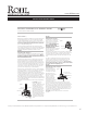
Supply fault / failure. See figure 4.
In order to determine and eliminate a supply fault or failure it will be
necessary to remove the
shower body from the installation. BEFORE
ATTEMPTING TO REMOVE THE SHOWER BODY ENSURE THAT BOTH HOT
AND COLD SUPPLIES ARE ISOLATED.
Take extreme care when working not to damage any of the finished
parts by protecting surfaces of tools with masking/insulating tape.
Undo the supply union nuts and slide them away as far as possible.
Undo the riser joint, slide the nut away from the joint and temporarily
se
cure out of the way with masking/insulating tape. As soon as the
seal is broken on the riser joint water will flow from the joint and the
shower outlet connected to the riser. Undo, but do not remove, the
grub screw in the backplate using a 2.5mm AF Allen Key.
Pull the shower body slowly forward, to release body from backplate,
and slowly downwards, to release riser joint. Remove body completely
from in
stallation. Place to one side to prevent damage. The seal
between the supply union and the shower body is made with an ‘O’
ring. They should remain in the groove in the supply unions. If they fall
out ensure that they are kept to one side to be re used. The filters in
the supply unions can now be removed and inspected for signs of
debris and cleaned. Before replacing the filters flush out the pipework
t
o ensure that any further debris is removed from the system and that
there is an adequate supply.
The supplies can easily be flushed out at this stage by simply turning
them on.
Re-assembly - This is the
reverse of the removal
procedure. Ensure that on both
installations that the ‘O’ ring
seals and filters remain in
position in the supply unions
and that the ‘O’ ring seals are
clean and undamaged. As a
preca
ution before re-assembly
make sure non-return valves
are operating freely by pushing
on the centre with a finger. A
small amount of water will fall
out when the non-return valve
opens.
E x p o s e d T h e r m o s t a t i c S h o w e r M i x e r
T r o u b l e s h o o t i n g
U . 3 5 5 2 L • U . 3 5 5 6 X • U . 5 5 5 0 L • U . 5 5 5 2 X
Figure 4
Riser Joint Nut
2.5mm
AF Allen Key
Grub Scew
O'Ring Seal
Supply Filters
Union Nut
Wall Rosette
Figure 5
Inlet Union
Non Return Valve
Figure 6
1/4 turn ceramic valve
Plastic Vernier Insert
Lever/Crosshead
Assembly
Lever Screw
Hood
2 Fit and seal, the correct length for your installation, a
3
/
4
”
NPT
male nipple (not supplied) into the female fitting so that no more
than
5
/
8
”
of thread is protruding from the wall surface.
3 Apply thread sealing material to shank and with rosette in place,
screw union onto shank. Turn union to required position.
4 Flush the plumbing system to remove plumbing residues prior to
fitting shower.
5 Temporarily
fit the shower body between the two unions and
adjust the position if necessary.
6 With the shower body still in position, mark the position of the
backplate on the wall.
7 Remove the shower body and using the backplate as a template,
with the grubscrew facing down, mark the positions of the fixing
holes.
8 Secure backplate to the wall using plugs and screws provided.
9 Place shower body into backplate and t
ighten grubscrew
sufficiently to hold body into position. Ensure that the ‘O’ ring
seals and filter meshes are in position between the surfaces of
the wall union and the shower inlet union.
10 Fully tighten union coupling nut onto shower inlet union by hand
only. If you need to use a wrench, protect nuts with a cloth or
tape.
11 Fully tighten grubscrew in backplate.
12 Slide rosette up to finished wall sur
face.
B E F O R E U S E
Carefully check the installation for leaks.
If further building work is to be carried out in the vicinity, cover
the thermostatic shower mixer with a plastic bag to avoid
damaging the finish.
C A R E & M A I N T E N A N CE
Wipe down after use to avoid water spotting and mineral build up.
Occasional cleaning with warm soapy water, followed by a polish with
a soft cloth is all that is required to keep
the plated finish in good
condition.
Do not use proprietary abrasive liquids, powders, or pads to clean the
shower. Do not use any products with ammonia bleach or limescale
remover. You will damage the plated finish and void your guarantee.
C H E C K L I S T
! Temperature of the hot water supply does not exceed 82
˚
C (180
˚
F)!
! Recommended minimum water supply pressure - 0.2 bar (2.9psi) !
! Recommended maximum
water supply pressure - 10 bar (145psi) !
! Ideal performance obtained with equal hot & cold pressures !
P R E P A R A T I O N
Flush the plumbing system before installing the shower. This is to
remove plumbing residues. This is especially important where
extensive plumbing work has been carried out.
The Hot supply should be on the left when viewed from the front
of the fit ting.
We recommend hot and cold su
pplies should have conveniently
placed isolating valves to accommodate any servicing
requirements.
If the bottom outlet is being utilized for a hand shower, rain bar,
or body sprays and the showerhead on the
top outlet is being used at the same time, it
is possible that there may be a temperature
variation between the outlets. If you need
to run two functions at once, the system
should be designed using
only one outlet.
Please ensure that the installation complies
with the local plumbing codes.
When fitting U3556, U3552 or U3552LS
they should be positioned to allow an air
gap of 2” above the tub rim (see diagram).
Check compliance with local plumbing
codes.
I N S T A L L A T I O N
1 Fit two
3
/
4
”
NPT male fittings into wall at 7
7
/
8
” centers.
E x p o s e d T h e r m o s t a t i c S h o w e r M i x e r
I n s t a l l a t i o n
U . 3 5 5 2 L • U . 3 5 5 6 X • U . 5 5 5 0 L • U . 5 5 5 2 X
2"
Tub Rim
5
/
8
" Max
3
/
4
" NPT
Wall
7
7
/
8
" Centers