
User's Manual


M7X and M7R Page 4-18 Installation
Back to Menu
External Signal Connections
External signal connections, except the external 10 MHz reference frequency, are made using one or
more of the thirteen RJ48 connectors fitted to the Interface panel. The panel is located as shown in
Fig 4-4 on page 4-6, and detailed in Fig 4-13. The 10 MHz reference frequency connector is detailed on
page 4-33.
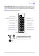
The pin-out of an RJ48 connector is shown in Fig 4-14.
Fig 4-13 Interface Panel
Fig 4-14 RJ48 Connector Pin-Out
Primary narrow-band audio and
signalling connections. See page 4-19.
Primary wideband audio and signalling
connections. See page 4-22.
WB (A)
NB (A)
WB (B)
NB (B)
Secondary narrow-band audio and
signalling connections. See page 4-21.
Secondary wideband audio and
signalling connections. See page 4-23.
Serial 1
FAC
E1
RCU
Tape
BIT
T1
Serial 2
Ethernet
Various system Facilities
connections. See page 4-24.
External BIT indication connections.
See page 4-25.
External tape recorder and loudspeaker
connections. See page 4-27.
Auto-tune filter and RCMS
connections. See page 4-26.
RS422 interface. See page 4-29.
VDL Mode 3 network computer, or split-site
Mode 2 base station connections. See page 4-31.
10/100Base-T ethernet network
connections. See page 4-32.
Co-located M7C RCU connections.
See page 4-28.
Digital voice switch or remote controller
connections. See page 4-30.
Pin 1
RJ48 Plug
Numbering is shown looking from the top of the connector.
The top is being viewed when the lever is on the bottom.