Operating Instructions Color CCTV Camera Model No. WV-CF504, WV-CF504E Before attempting to connect or operate this product, please read these instructions carefully and save this manual for future use. The model number is abbreviated in some descriptions in this manual.
Preface About the user manuals The operating instructions of the camera consist of 2 sets: these operating instructions (PDF) and Installation Guide. This document explains how to configure the settings of the camera. Refer to the installation guide for further information about how to install the camera. Adobe® Reader® is required to read PDF. When the Adobe® Reader® is not installed on the PC, download the latest Adobe® Reader® from the Adobe web site and install it.
Contents Preface................................................................................ 2 About the user manuals.................................................. 2 Trademarks and registered trademarks.......................... 2 About the setup menus....................................................... 4 Setup menu list............................................................... 4 Basic operation............................................................... 5 Screen transition diagram.......
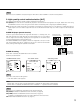
About the setup menus Performing each setting item in the setup menu should be completed in advance to use this unit. Perform the settings for each item in accordance with the conditions of the camera shooting area. The following is an example of setup procedure when LANGUAGE is set to ENGLISH. Setup menu list Setup item CAMERA ID CAMERA Description This item specifies the camera title.
Basic operation The description below explains how to operate the setup menu basically. The operations in the setup menu are performed with the operation buttons after calling up the setup menu on the connected video monitor. Refer to the installation guide for further information about the operation buttons. The operations in the setup menu can also be performed through the system controller (option).
Screen transition diagram Top screen "CAMERA ID" screen MODEL WV-CF504 CAMERA ID OFF CAMERA SYSTEM BACK-FOCUS SPECIAL LANGUAGE END **CAMERA ID** 0123456789 ABCDEFGHIJKLM NOPQRSTUVWXYZ ().,'":;&#!?= +-*/%$ SPACE POSI RET TOP END RESET ................
Camera title setting [CAMERA ID] This item specifies the camera title. The camera title that indicates the camera location and other information about the camera is created with alphanumerics and symbols, and is displayed on the screen. The camera title is named with up to 16 characters. Follow the procedure below to specify the camera title.
Camera operation setting [CAMERA SETUP] The following describes the camera operation settings. The following settings can be configured on the "CAMERA SETUP" screen displayed from the top screen. Refer to page 5 for how to call up the screen. The settings configured on the "CAMERA SETUP" screen will be saved as a scene file. "CAMERA SETUP" screen q w e r t y u i o **CAMERA SETUP** SCENE1 ALC ALC SHUTTER OFF AGC ON(HIGH) SENS UP OFF WHITE BAL ATW1 DNR HIGH BW MODE AUTO1 i-VMD RET TOP END 1.
Step 5 Move the cursor to "SCENE1" and press the right or left button to select "SCENE1" to resume normal operation. 2. Light quantity control method selection [ALC] The method of controlling the quantity of light is selected from the following. ALC (default): The iris of the lens is automatically adjusted in accordance with the brightness of a subject. Select "ALC" when using the SUPER-D5 function or when using an ALC lens. Refer to the following when configuring the SUPER-D5 settings.
Note: • When "ON" or "ON(i-VMD)" is selected for "SUPER-D5", the following settings will be restricted. SHUTTER: Only OFF and 1/100 are available. (☞ page 11) SENS UP: Only "OFF" and "AUTO" become available. (☞ page 12) • When "ON" or "ON(i-VMD)" is selected for "SUPER-D5", a shadow (black line) may appear at the boundary between a brighter area and a darker area. This is not a malfunction.
"ALC CONT" screen Mask setting screen **ALC CONT**(1) BACK LIGHT COMP SUPER-D5 OFF MASK SET LEVEL MANUAL ABS Area setting screen **AREA POSITION **(1) PUSH SW UPPER LEFT ...|... 0 + RET TOP END DEL RET TOP END Step 2 Mask bright areas. Use the up, down, right, and left buttons to select an area to be masked and press the setting button. When the selected area is masked, the masked area will start blinking (between stripes and white screen).
Note: • When "ALC" is set to "ALC+" (☞ page 9), "---" appears and the electronic shutter function cannot be activated. • If the controller, WV-CU254 or WV-CU204 is used, SW LED and the status of "SHUTTER" are not correctly displayed. 4. Gain control setting [AGC] Select a gain control setting from the following. ON (HIGH) (default)/ON (MID)/ON (LOW): Automatically increases the gain to make the screen brighter when the illuminance of the subject becomes darker.
AWC: Activates the automatic white balance control mode. This adjustment is suitable for a location where a light source is stable. The adjustment of the color temperature ranges from approx. 2 000 K to 10 000 K. When "AWC" is selected, the white balance needs to be adjusted. When "AWC" is selected, follow the steps below to adjust the white balance.
Step 2 Move the cursor to "R" and "B" and use the right or left button to fine adjust the level for each. When the level indicator moves in the "+" direction, the color becomes deeper, and when the level indicator moves in the "–" direction, the color becomes lighter. 7. Digital noise reduction function setting [DNR] The digital noise reduction function reduces noise automatically under the condition of low illuminance.
HIGH (default): Switches from color to black-and-white images when the ambient brightness (illuminance) of the camera is approx. 0.2 lx or less. Note: • To obtain color images, a sufficient level of illuminance (approx. 30 lx or more) is required. • The switching illuminance level varies with subjects, light sources, and lenses. • The switching illuminance level varies in accordance with AGC setting. (☞ page 12) • The switching illuminances described above are reference values.
Perform the settings relating to the motion detection Perform the settings relating to the motion detection as follows. It is possible to detect only objects that moves to the direction specified in advance or objects that keeps on moving for a certain duration. Up to 4 motions can be simultaneously detected. Follow the procedure below.
Step 6 Set the detection sensitivity and the minimum size of objects detected. Perform the setup while viewing the detection result displayed on the screen.
Step 4 Move the cursor to "AREA" and select the area for which the detection of appearance/disappearance of stationary objects is to be set. ALL (default): All areas will be set as the detection area. SETUP: When the setting button is pressed after selecting "SETUP", up to 2 areas can be set as the detection area. Refer to the description below for how to configure the settings. Step 5 Move the cursor to "SENSITIVITY" and press the setting button. → The "SENSITIVITY" screen appears.
Step 4 Use the up, down, right, and left buttons to determine the left upper position of the area to be set and press the setting button. Note: • The area corresponding to the selected number will be displayed in a green frame, while the other set areas are shown in a white frame. Step 5 Use the up, down, right, and left buttons to determine the right lower position of the area to be set and press the setting button.
Configure frame display Follow the procedure below. "CAMERA SETUP" screen **CAMERA SETUP** SCENE1 ALC ALC SHUTTER OFF AGC ON(HIGH) SENS UP OFF WHITE BAL ATW1 DNR HIGH BW MODE AUTO1 i-VMD RET TOP END "i-VMD SETUP" screen **i-VMD SETUP**(1) MOTION DET OBJECT DET OFF SCENE CHANGE OFF INDICATOR ALARM OFF CONT RET TOP END Step 1 Move the cursor to "i-VMD" and press the setting button. → The "i-VMD SETUP" screen appears.
Camera system setting [SYSTEM SETUP] Performs the settings relating to the camera system such as synchronization, alarm input/output terminal, and privacy zone. The following settings can be configured on the "SYSTEM SETUP" screen displayed from the top screen. Refer to page 5 for how to call up the screen. "SYSTEM SETUP" screen !0 !2 !4 **SYSTEM SETUP** INT PANASONIC !1 SYNC LENS !3 PRIVACY ZONE STABILIZER EL-ZOOM UPSIDE-DOWN !5 OFF OFF OFF OFF RET TOP END 10.
Step 1 Set "SYNC" to "LL" and press the setting button. → The "SYNC" screen appears. Step 2 Connect the video output signal and external synchronizing input signal of the camera to a 2-input oscilloscope, and move the cursor to "COARSE". Step 3 Adjust the oscilloscope to the vertical rate, and extend the vertical synchronizing part of the oscilloscope. Move the cursor horizontally with use of the right or left button to roughly adjust the vertical phase. The phase can be adjusted in 16 steps by 22.
Step 3 Move the cursor to "POSITION" and press the setting button. Step 4 Use the up, down, right, and left buttons to determine the left upper position of the zone to be set and press the setting button. Step 5 Use the up, down, right, and left buttons to determine the lower right position of the zone to be set and press the setting button. → The asterisk mark "*" will be displayed after the number and the zone setting will be saved.
14. Electronic zoom setting [EL-ZOOM] Select "On" or "Off" to determine whether or not to use the electronic zoom. When "ON" is selected, the zoom factor and the panning/tilting settings can be configured. ON: Uses the electronic zoom. OFF (default): Does not use the electronic zoom. Follow the procedure below.
Back focus setting [BACK-FOCUS SETUP] Selects the back focus setting type and performs fine adjustment. The following setting can be configured on the "BACK-FOCUS SETUP" screen displayed from the top screen. Refer to page 5 for how to call up the screen. The lens adjustment (☞ Installation Guide) shall be performed before the back focus adjustment. The back focus adjustment is performed by changing the distance between the lens and focal point. Follow the procedure below.
Step 3 Move the cursor to "C/L ← → B/W" and select the back focus adjustment type from the following: AUTO (default): Adjusts the back focus function automatically and corrects out of focus when switching between color and blackand-white images. PRESET: Performs the preset movement to each specified back focus position when switching between color and black-and-white images.
Special menu setting [SPECIAL SETUP] The special menu setup is performed including the setting of the camera image quality and the communication configuration when a receiver is used. The following settings are to be configured on the "SPECIAL SETUP" screen displayed from the top screen. Refer to page 5 for how to call up the screen. "SPECIAL SETUP" screen **SPECIAL SETUP** ...|...128 CHROMA GAIN ...|... 32 AP GAIN ... |... 32 PEDESTAL ...|... 0 HUE + PIX OFF CAMERA RESET PUSH SW SER.NO.
Flaw compensation [PIX OFF] Flaws in the displayed camera image are corrected. Up to 16 points can be corrected. Follow the procedure below. "SPECIAL SETUP" screen "PIX OFF" screen **SPECIAL SETUP** ...|...128 CHROMA GAIN ...|... 32 AP GAIN ...|... 32 PEDESTAL ...|... 0 HUE + PIX OFF **PIX OFF** CAMERA RESET PUSH SW SER.NO.
Language selection [LANGUAGE SETUP] A language for the setup menu is selected from the following: The language selection can be made on the "LANGUAGE SETUP" screen displayed from the top screen. Refer to page 5 for how to call up the screen.
Shortcut operation Use of a system controller with the "camera function" button allows users to perform the shortcut settings with use of the numeric keypad and camera function button.
System controller operation Setting contents [2] + [1] + [1] + [Camera function] Scene change ON [2] + [1] + [2] + [Camera function] Scene change OFF [2] + [1] + [3] + [Camera function] Scene file 1 [2] + [1] + [4] + [Camera function] Scene file 2 [2] + [1] + [5] + [Camera function] Gain (AGC), 1 step up [2] + [1] + [6] + [Camera function] Gain (AGC), 1 step down 31
For U.S. and Canada: For Europe and other countries: Panasonic System Networks Company of America, Unit of Panasonic Corporation of North America Panasonic Corporation www.panasonic.com/business/ For customer support, call 1.800.528.6747 Three Panasonic Way, Secaucus, New Jersey 07094 U.S.A. Panasonic Canada Inc. 5770 Ambler Drive, Mississauga, Ontario, L4W 2T3 Canada (905)624-5010 www.panasonic.ca © Panasonic System Networks Co., Ltd. 2011 http://panasonic.