
Outback Power GS4048A and GS8048A Installation Manual


Installation
900-0160-01-00 Rev A 21
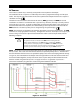
Table 4 DC Conductor Size and Torque Requirements
Inverter Nominal DC Amps
(Minimum, per breaker)
(Derated 125%)
Conductor Size
(Minimum, per breaker)
Breaker Size
GS8048A
104
2/0 AWG 0.105 in²) or 70 mm²
175 Adc/AIC 10kA
GS4048A
104
2/0 AWG 0.105 in²) or 70 mm² 175 Adc/AIC 10kA
Terminal Location Torque Requirements
Inverter DC Terminals 60 in-lb (6.9 Nm)
Battery Terminals See battery manufacturer’s recommendations
When installing DC cables:
Make certain DC circuit breakers are turned to the off position, or fuses are removed, before proceeding.
Battery positive (+) and negative (–) cables should not exceed 10 feet (3 m) each to reduce voltage loss and other effects.
The modular construction of the GS8048A requires the use of two DC circuit breakers or fuses.
The cables for each overcurrent device must
each
be sized appropriately. Alternately, a single cable or bus may be used
if sized to the minimum total ampacity. The cables listed above are for each inverter in a system. In a multiple-inverter
system, each inverter requires its own cables and overcurrent devices of the size indicated.
Install all overcurrent devices on the positive cable.
Tie, tape, or twist positive and negative cables together to reduce self–inductance. Run positive and negative cables
through the same knockouts and conduit.
NOTE
: Do not install hardware in a different order from the illustrations shown in
Error! Reference source not found.
. In
all cases the battery cable lug must be the first item installed. It must make solid contact with the surface.
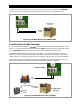
Figure 16 DC Cable Hardware (Radian inverter)
If the battery cables are connected directly to the Radian
inverter, the hardware should be arranged as shown in image A.
The inverter’s battery terminal is a threaded hole which accepts
a hex bolt (provided). The battery cable lug must have a
0.79 cm (5/16") diameter hole.
If the inverter is installed with the GS Load Center (GSLC),
follow GSLC instructions for cable and hardware installation.
The hardware should be arranged according to the appropriate image below.
GSLC models used with the GS8048A inverter are equipped with a DC positive (+) plate. The plate accepts an M8 hex
bolt and nut. See image B.
GSLC models used with the GS4048A inverter do not use the DC positive plate. The cable lugs are connected to the
DC disconnect, which uses a threaded M8 stud. See image C.
All GSLC models connect the battery negative cables to the shunt, which is threaded for 3/8” bolts. See image D.
Battery Cable
Lug
Flat Washer
M8-1.25 Hex Bolt
Mounting
Surface
Lock Washer
Battery
Cable Lug
M8-1.25 Hex Bolt
Lock Washer
Flat
Washer
DC
Positive
(+) Plate
Nut
Flat Washer
GS-SBUS
Battery
Cable Lug
Flat Washer
Lock Washer
Shunt
B
DC Disconnect
Battery
Cable Lug
Battery Monitor
Ring Terminal
Charge
Controller Ring
Terminal
Flat Washer
Lock Washer
Nut
M8 Stud
C
D
A
3/8” Hex Bolt