
User Manual


FUSB307BGEVB
www.onsemi.com
2
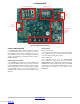
Figure 3. Evaluation Board Layout
mUSB
to PC
Load Switches
for Sinking/
Sourcing
Power
LED IndicatorsMCU Program/Debug
External Power Inputs
Type−C
Connector
POWER CONFIGURATION
The FUSB307B evaluation board is designed to be able to
be powered from just the PC connection or powered
externally based on the testing requirements. To use the
external VDD to the device, take the jumper off of JP1 and
connect external VDD to the middle post of JP1, which is
FUSB307B VDD.
Power Supplied from Board
The FUSB307B can fully operate from the VBUS input
of the micro-B USB receptacle J3. To operate the evaluation
board, the USB power should be provided to the board over
the micro-B USB. Then, the on board regulator (LDO)
generates VDD, which is 3.3 V for device supply. Once
valid USB power is provided, the indicator LED, 3.3 V, is
turned on.
I
2
C Connection
Direct I
2
C Connection
Customers that want to directly connect their I
2
C masters
to the evaluation board can connect the I
2
C master signals
to the SCL, SDA, and INT_N test points.
PC I
2
C Connection
The evaluation board uses an STM32F072CB
micro-controller-unit (mcu) as an I
2
C master to control the
FUSB307B. This is the communication method used by the
FUSB307B GUI. By connecting the PC to the micro-B USB
receptacle J3, the evaluation board automatically powers the
microcontroller and connects the I
2
C master to the
FUSB307B.
Downloaded from Arrow.com.Downloaded from Arrow.com.