
User's Manual


V740 RFID READER/WRITER, ANTENNA 2005-09, REV0.1
OPERATION MANUAL
11 of 56 ©OMRON CORPORATION 2005
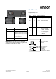
One to four OMRON Bi-static antennas(V740-
HS02CA,02C) can be connected to the reader,
depending on the application requirements. The lower
row of silk-screen markings on the reader identifies
the port number and antenna connections.
Note: Upper row of silk-screen marking on the reader
is reserved for future use.
1. Connect required UHF antennas to the antenna
ports on the reader .
IMPORTANT: Connect antennas to the antenna
ports before applying power to the reader. Any
antenna port not having an antenna connected to
it will be disabled when the reader is powered on.
Antenna Connection : V740-BA50C22A-US
Note: With the two antenna configuration, there is
a possibility that a tag may be read by an inactive
antenna if the tag is located with in approximately
20 cm of the inactive antenna.
2. Verify that all antennas are securely connected.
3. Connect the reader to the network by plugging a
Shielded Ethernet cable into the Ethernet port.
or
Connect the reader to a PC (personal computer)
by plugging a crossover Shielded Ethernet cable
into the Ethernet port.
Note: If DHCP is to be used, then the network
and server must be connected before powering
up the reader. If a DHCP server is not found the
reader will fall back to the IP address:
“10.0.0.101”.
Note: If NTP is to be used, then the network must
be connected and the server must be available
before powering up the reader. If a NTP server is
not found. The reader will not set the current time.
4. Plug the power adapter provided with the reader
into the DC power input connector. Then connect
the AC power cord to a power outlet.
While the reader is powering up, one green light
will be on. After the reader finishes its power-on
self-test, approximately 45 seconds, the green
light will pulse. The reader is now ready for
operation.
Antenna Cable x4
(
V740-A01
)
Antenna x2
(
V740-HS02CA
)