
Datasheet


SA56004X All information provided in this document is subject to legal disclaimers. © NXP B.V. 2013. All rights reserved.
Product data sheet Rev. 7 — 25 February 2013 17 of 43
NXP Semiconductors
SA56004X
Digital temperature sensor with overtemperature alarms
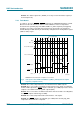
7.9.2 T_CRIT output
The T_CRIT output is LOW when any temperature reading is greater than the preset limit
in the corresponding critical temperature setpoint register. When one of the T_CRIT
setpoint temperatures is exceeded, the appropriate status register bit, 1 (RCRIT) or 0
(LCRIT), is set.
After every local and remote temperature conversion the status register flags and the
T_CRIT
output are updated. Figure 7 is a timing diagram showing the relationship of
T_CRIT
output, Status bit 1 (RCRIT) and the remote critical temperature setpoint (RCS),
and critical temperature hysteresis (TH) with remote temperature changes. Note that the
T_CRIT
output is de-activated only after the remote temperature is below the remote
temperature setpoint, RCS minus the hysteresis, TH. In the interrupt mode only, the
Status register flags are reset after the Status register is read.
Event A: T_CRIT goes LOW and Status bit 1 (RCRIT) is set HIGH when Remote
Temperature exceeds RCS, Remote T_CRIT Setpoint.
Event B: Remote Temperature goes below RCS TH. T_CRIT
is de-activated, but
Status register remains unchanged.
Table 17. ALERT response bit assignment
ALERT response bit Device address bit Function
7 (MSB) ADD6 address bit 6 (MSB) of alerted device
6 ADD5 address bit 5 of alerted device
5 ADD4 address bit 4 of alerted device
4 ADD3 address bit 3 of alerted device
3 ADD2 address bit 2 of alerted device
2 ADD1 address bit 1 of alerted device
1 ADD0 address bit 0 of alerted device
0 1 always logic 1
Fig 7. T_CRIT temperature response timing
002aad217
RCS
RCS − TH
Status register bit 1
(RCRIT)
ABC
remote temperature
T_CRIT output