
Datasheet


ISD5100 SERIES
Publication Release Date: Oct 31, 2008
- 33 - Revision 1.42
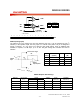
6.4.6 Ana Out Description
Chip Set
AN A O U T +
AN A O U T –
*VOL
*FILTO
*SUM2
3 (AO S2,AOS1,AOS0)
* FTHRU
1
(AOPD)
*INP
*SUM1
(1 Vp - p m a x. f r om A UX IN o r ARRA Y)
(69 4 mVp-p ma x. fro m mi crop ho ne inp ut)
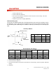
INS0
15141312111098 76 54 32 10
AI G 1
AI G 0 A I PD A XG 1 AX G 0 A XPD
AO S2 A O S1 A O S0 AO PD
OPS1 O PS0 O PA 1 O PA 0 V LPD
CFG0
6.4.7 Analog Inputs
Microphone Inputs
The microphone inputs transfer the voice signal to the on-chip AGC preamplifier or directly to the ANA
OUT MUX, depending on the selected path. The direct path to the ANA OUT MUX has a gain of 6
dB so a 208 mV p-p signal across the differential microphone inputs would give 416 mV p-p across
the ANA OUT pins. The AGC circuit has a range of 45 dB in order to deliver a nominal 694 mV p-p
into the storage array from a typical electric microphone output of 2 to 20 mV p-p. The input
impedance is typically 10k.
The ACAP pin provides the capacitor connection for setting the parameters of the microphone AGC
circuit. It should have a 4.7 µF capacitor connected to ground. It cannot be left floating. This is
because the capacitor is also used in the playback mode for the AutoMute circuit. This circuit reduces
the amount of noise present in the output during quiet pauses. Tying this pin to ground gives
maximum gain; to VCCA gives minimum gain for the AGC amplifier but will cancel the AutoMute
function.
AOS2 AOS1 AOS0 SOURCE
0 0 0 FTHRU
0 0 1 INP
0 1 0 VOL
0 1 1 FILTO
1 0 0 SUM1
1 0 1 SUM2
1 1 0 N/C
1 1 1 N/C
AOPD CONDITION
0 Power Up
1 Power Down
*DIFFERENTIAL PATH