
User Guide


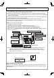

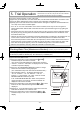


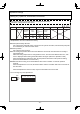
Table Of Contents

- 13 -
(Device No., Data No., Data)
(Device No.)
Temperature display
Temperature switch
(Changing the Data No.)
Power Button
Flow Meter Alarm
Set Button
5. Trial Operation
Connect electrical power to each of the units.(1)
Open the gas shutoff valve, the main water valve, and the water shutoff valves on all of the units.(2)
Turn the power ON with the remote controller. (The Operation Lamp will light up.)(3)
Slowly open a hot water fi xture and confi rm that the units ignite in sequence and that the Burner (4)
On Lamp on the remote controller lights.
The installer should test operate the system, explain to the
customer how to use the units, and give the owner the Installation
and Operation Manual before leaving the installation.
Turn the Power button "ON".(1)
Press the temperature up and down buttons (2) △ and ▽
simultaneously for more than 2 seconds.
(The remote control will display the maintenance monitors.)
"Unit No.", "Data No." and "Data" are displayed on the remote *
controller temperature display.
Press the "FLOW METER ALARM SET" button to change (3)
which unit's information in being displayed.
(The combustion lamp of the selected unit will fl ash twice.)
When switching "Unit No.", the display will change from *
"5C→01→Data No."→"01→02→Data No."→"02→03 →
Data No."• • •"(Last Unit)No.→5C→OFF" when the "FLOW
METER ALARM SET" button is pressed.
If the "FLOW METER ALARM SET" button is not pushed to
change the Unit No., the Data No. for that Unit will then be
displayed on the remote controller.
Press the temperature up or down buttons (4) △ or ▽ to select
Data No.14. The water fl ow through that heater will be
displayed.
Repeat (2) - (3) for all water heaters. Adjust so that the total (5)
water fl ow of all devices is 2 GPM or more.
Press the temperature up and down buttons (6) △ and ▽
simultaneously for over 2 sec. to return to the temperature
display.
If an "11" or "12" error code fl ashes on the remote controller, there may be air in the gas line.•
Hit the Power Button ON and OFF a few times and then open the fi xture again to try igniting the
unit again.
If this fi xture does not cause all of the units to ignite, test the rest of the units by switching which •
is
the primary unit by pressing either the Maximum or Minimum Manifold Pressure Set Button on the
circuit board of the unit.
Operate all of the units and confi rm that the water temperature corresponds to the temperature set •
on the remote controller. Set the remote to the lowest temperature to maximize water fl ow.
If the water temperature is hotter than the set temperature, check to make sure that the remote is
connected to the system controller, and that the system controller is connected to the other units.
If the units do not operate properly, refer to the Troubleshooting section of the Owner's Manual.•
After the test operation, clean any debris off of the fi lter on the water inlet.*
Checking Water Flow (Maintenance Monitors) Necessary only for recirculation systems
N-084M(-DV)(-ASME), N-132M(-ASME), N-1321M-ASME, NC380-SV-ASME, N-0931M(-DV,-OD)(-ASME),
NC250-SV(-DV)-ASME, N-0841MC(-DV), NCC199-SV(-DV), N-0842MC(-DV)