
User's Manual


Test Set Calibration – continued
FEB 2005 1X SC 4812T Lite BTS Optimization/ATP 3-109
PRELIMINARY
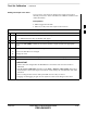
Table 3-34: Non–Duplexed RX Test Cabling Using Signal Generator and Spectrum Analyzer
Calibration Procedure
n ActionStep
4 Change the Test Set–up to the one shown in Detail “B” (lower portion of Figure 3-43) to measure
the output at the Customer’s RX Frequency.
– 824.7–848.31 MHz for North American Cellular
or
– 1850–1910 MHz for North American PCS
5 Record the value measured with the Detail “B” Test Set–up.
6 Calibration Factor = (Value measured with Detail “A” Set–up) – (Value measured with Detail “B”
Set–up)
Example: Calibration Factor = –12 dBm – (–14 dBm) = 2 dB
* IMPORTANT
The Short Test Cable is used for Test Equipment Set–up Calibration Only.
– It is not part of the Final Test Set–up.
After Calibration is completed, do not re-arrange any cables.
– Use the Test Cable Configuration as–is to ensure Test Procedures use the correct Calibration
Factor.
Spectrum
Analyzer
Signal
Generator
A
B
Spectrum
Analyzer
SHORT
TEST
CABLE
CONNECTION TO THE COMMUNICATIONS
SYSTEM ANALYZER RF OUTPUT
CONNECTOR DURING RX MEASUREMENTS
Signal
Generator
BULLET
CONNECTOR
TX
Test
Cable
SHORT TEST
CABLE
CONNECTION TO THE BTS RX ANTENNA
CONNECTOR DURING RX ATP
IMPORTANT: IF BTS TX/RX SIGNALS ARE
DUPLEXED, THE RX TEST CABLE CONNECTS
TO THE DUPLEXED ANTENNA CONNECTOR
AND MUST USE/BE CALIBRATED WITH THE 30
DB DIRECTIONAL COUPLER AND 20 DB
IN–LINE ATTENUATOR. SEE FIGURE 3-42.
Figure 3-43: Calibration Set–up for Non–Duplexed RX Test Cabling
using a Signal Generator and a Spectrum Analyzer
3