
User Manual


RF Cabinet Interconnect Cables – continued
Jan 2002
H-25
SC4812ET BTS Optimization/ATP — CDMA LMF
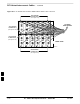
50 Pair Punchblock
The 50 pair punchblock is the main interface point for RGPS, span lines,
customer I/O, Power Cabinet alarm lines, and the modem. The
punchblock provides primary protection for all lines. Refer to
Figure H-18 and Table H-4 for punchblock pin–out.
SC4812ET Span Line Labeling for Span B and Span C is
swapped
– On the SC4812ET’s, the span cabel internal to the base
station that connects the 50 pin header on the I/O plate to
the CSU has Span B and Span C (RJ–45) connectors
mis–labeled.
– CFE will punch down the span on the 50 pair bunchblock
as per Motorola documentation and punchdown chart.
When conecting the span input to the CSU re–label
“Span B” cable to”Span C” cable to “Span B”. Connect
to CSU as per documentation
– Note: The labeling issue on the cable from the I/O plate
to the CSU Part Number 3086601H01 Rev C shall be
corrected on revision “D” to address this issue. The cut
over date to Rev. D will be approximately January 30,
2001.
CAUTION
A wiring discrepancy exists between the manuals and the
frame for remote GPS.
– The TX and RX are reversed in the ETIB, leading to in-
operability of the RGPS. The RGPS will not work in ei-
ther a single standalone or multiple frame configuration.
– Swap the White and White/Bk wires to punch pins 44T
and 44R. The Green and Green/Bk go to 45T and 45R.
This will correct non–expansion configurations.
– Single frame and expansion BTSs without RGPS can use
this workaround as a permanent solution.
– For expansion with RGPS required a new cable (P/N
3086433H10 ) will correct the problem.
CAUTION
H