
User Manual


Troubleshooting
68P09255A57-2
Aug 2002
SC4812ET Optimization/ATP Manual Software Release R16.1.x.x
PRELIMINARY
6-22
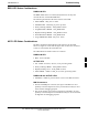
Figure 6-3: MCC24/8E Front Panel LEDs and LED Indicators
PWR/ALM LED
LENS
(REMOVABLE)
ACTIVE LED
PWR/ALM ACTIVE
PWR/ALM
OFF − operating normally
ON − briefly during power−up and during failure
conditions
ACTIVE
LED OPERATING STATUS
RAPIDLY BLINKING − Card is code−loaded but
not enabled
SLOW BLINKING − Card is not code−loaded
ON − card is code−loaded and enabled
(INS_ACTIVE)
COLOR
GREEN
RED
RED
ON − fault condition
SLOW FLASHING (alternating with green) − CHI
bus inactive on power−up
An alarm is generated in the event of a failure
FW00224
LPA Shelf LED Status Combinations
LPA Module LED
Each LPA module contains a bi-color LED just above the MMI
connector on the ETIB module. Interpret this LED as follows:
GREEN — LPA module is active and is reporting no alarms (Normal
condition).
Flashing GREEN/RED — LPA module is active but is reporting an
low input power condition. If no BBX is keyed, this is normal and
does not constitute a failure.
Flashing RED — LPA is in alarm.
Span Problems
(No Control Link)
Follow the procedure in Table 6-29 when troubleshooting a control link
failure.
6