
Service Manual


Nedap Velos – RealTime Heat detection service manual GB Manual version 1.6 / Page 35
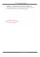
Appendix F Installing more than one antenna
1. Mount the V-boxes 1 (with the antenna reader) and the V-box 2 (process unit with the power
supply and the VPU controller) on a wall. Pay attention to the maximum distance. See
Appendix E for more information about mounting the V-boxes.
The maximum cable length between the VPU and the last VP4101 is 200 meter
if only VP4101 readers are connected. Connect maximum 4 VP4101 readers.
2. Connect the VPU controller to the VP4101 antenna readers and to a PC.
1. VPU controller
(VP8001) in process
unit
2. VP4101 reader
3. Antenna
4. Network or PC
5. Communication cable
6. UTP cat5 cable
Figure 18. Overview process unit connected to one or more VP4101 readers
Prepare the length of the blue communication cable for the distance between the VPU and
the first VP4101 and prepare more cable for the distance between the VP4101 readers.
The maximum cable length between the VPU and the last VP4101 is 200 meter.
Figure 19. Connecting VPU and reader and the maximum cable length
Put the communication cables through the cable glands, connect the communication cable
to the connectors and plug the connectors in the VPU controller and the VP4101. See
chapter 5 for more information and see the next page for a detailed wiring scheme for the
communication cable between the last two VP4101 readers.
Process
unit
← Max. 200 m. →
Last
VP4101
(max 4)
First
VP4101
VPU
6
L
e
n
gt
h
of
c
or
ri
d
or
(
m
)
1
1
L
e
n
gt
h
of
c
or
ri
d
or
(
m
)
4
L
e
n
gt
h
of
c
or
ri
d
or
(
m
)
5
L
e
n
gt
h
of
c
or
ri
d
or
(
m
)
2
L
e
n
gt
h
of
c
or
ri
d
or
(
m
)
3
1
L
e
n
gt
h
of
c
or
ri
d
or
(
m
)
VP4101
VP4101
VP4101
2
L
e
n
gt
h
of
c
or
ri
d
or
(
m
)
2
L
e
n
gt
h
of
c
or
ri
d
or
(
m
)
3
1
L
e
n
gt
h
of
c
or
ri
d
or
(
m
)
3
1
L
e
n
gt
h
of
c
or
ri
d
or
(
m
)
5
L
e
n
gt
h
of
c
or
ri
d
or
(
m
)
5
L
e
n
gt
h
of
c
or
ri
d
or
(
m
)