
Datasheet


Flyport Wi-Fi and Ethernet Programmer's guide framework 2.3 (rev 1.0) www.openpicus.com
Digital I/Os Functions
First of all initialize the pin as Digital Input or as Digital Output → IOInit(pin name, type);
For example:
Set pin 6 Digital output → IOInit(p6, out);
Set pin 5 Digital input → IOInit(p5,in);
How to change the state of a Digital Output → IOPut(pin name, value);
For example:
IOPut(p6, on); //sets the pin to high voltage value (3,3V)
IOPut(p6, off); //sets the pin to low voltage value (0V)
IOPut(p6, toggle); //toggles the state of the pin (H to L or opposite)
The “on” keyword is associated to a high voltage level, so a “TRUE” logical state. In a similar way the
“off” keyword is associated to a low voltage level, so a “FALSE” logical state.
Note: The keywords “on”, “off”, and “toggle” are case insensitive.
How to read the state of a Digital Input → IOGet(pin name);
For example:
IOGet(p5); //will return the value of pin 5 : on(1) or off(0)
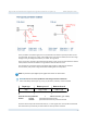
How to enable the internal pull-up or pull-down resistor of a Digital Input
pin 5 digital input with internal pull-up resistor → IOInit(p5, inup);
pin 5 digital input with internal pull-down resistor → IOInit(p5, indown);
QUESTION: What is the use for pull-up and pull-down resistors in Flyport's input pins?
Pull-up and pull-down resistors are always used to avoid floating voltages on input pins. With a pull-
up resistor we connect an input pin to a high voltage reference (3.3V), and with a pull-down resistor
we connect the pin to a low voltage reference (ground). Of course you can always change the input
value with another voltage source, or with a switch, as shown in the figure below:
12