OPERATOR’S MANUAL Model Numbers E662H, E642E 614E, E644E E664F, E6A4E Model Style 4 Shown IMPORTANT: READ SAFETY RULES AND INSTRUCTIONS CAREFULLY Warning: This unit is equipped with an internal combustion engine and should not be used on or near any unimproved forestcovered, brush-covered or grass-covered land unless the engine’s exhaust system is equipped with a spark arrester meeting applicable local or state laws (if any).
SECTION 1: IMPORTANT SAFE OPERATION PRACTICES WARNING: THIS SYMBOL POINTS OUT IMPORTANT SAFETY INSTRUCTIONS WHICH, IF NOT FOLLOWED, COULD ENDANGER THE PERSONAL SAFETY AND/OR PROPERTY OF YOURSELF AND OTHERS. READ AND FOLLOW ALL INSTRUCTIONS IN THIS MANUAL BEFORE ATTEMPTING TO OPERATE YOUR SNOW THROWER. FAILURE TO COMPLY WITH THESE INSTRUCTIONS MAY RESULT IN PERSONAL INJURY. WHEN YOU SEE THIS SYMBOL-HEED ITS WARNING.
• Never operate the machine at high transport speeds on slippery surfaces. Look behind and use care when backing. • If the snow thrower should start to vibrate abnormally, stop the engine and check immediately for the cause. Vibration is generally a warning of trouble. • Never direct discharge at bystanders or allow anyone in front of unit.
SECTION 2: FINDING YOUR MODEL NUMBER This Operator’s Manual is an important part of your new snow thrower. It will help you assemble, prepare and maintain your snow thrower. Please read and understand what it says. Before you start to prepare your snow thrower for its first use, please locate the model plate and copy the information from it in this Operator’s Manual. The information on the model plate is very important if you need help from your dealer or the MTD customer support department.
SECTION 4: CONTENTS OF HARDWARE PACK Lay out the hardware according to the illustration for identification purposes. Parts are illustrated approximately one-half size. Part numbers are shown in parentheses. (Hardware pack may contain extra items which are not used on your unit.
SECTION 5: ASSEMBLY INSTRUCTIONS IMPORTANT: After assembly, service engine with Attaching the Handle Assembly. (Hardware A and E) gasoline, and check oil level as instructed in the separate engine manual packed with your unit. Lay loose parts out on flat surface. NOTE: All references to right or left side of the 1. Handle Panel snow thrower are determined from behind the unit in the operating position. UNPACKING 2. Right Handle 5. Traction Drive Control Grip 3. Left Handle 6.
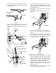
5. Secure with hex bolt, spacer and lock nut. See Figure 6. (Do not overtighten this bolt as it will prevent the grips from automatically returning to their upright position.) 6. Repeat process for the right side Traction Drive Control Grip. 7. Lay handle assembly behind snow thrower. See Figure 7. 3. Insert curved end of the Z fitting into the top hole in the triangular metal tab on the auger control grip. See Figure 5. Triangle Metal Tab Auger Control Grip “Z” Fitting Hex Bolt Figure 5 4.
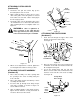
Traction Drive Clutch Shift Lever Ferrule Flat Washer Hairpin Clip Shift Rod Flat Washer Hairpin Clip Figure 9 Shift Arm Assembly Models 642 and 662 Figure 11 Flat Washer Lock Washers Shift Lever Hairpin Clip Cable Roller Hex Bolt Guide Handle 3/4” Long Tab Hex Bolt 1-3/4” Long Ferrule Shift Rod Flat Washer Figure 10 Hairpin Clip ATTACHING SHIFT ROD (Hardware D) Shift Arm Assembly Models 614, 644, 664, and 6A4 1. Place the shift lever in the fastest forward speed position. Figure 12 3.
ATTACHING CLUTCH CABLES (Hardware D) Chute Assembly 1. Thread the hex jam nuts all the way up the threaded portion of the “Z” ends. Hex Bolt 2. Make certain all cables are in the grooves of the cable roller guides. The roller guides are located in the lower rear of the unit. Lift the clutch grip in the raised (up) position. 3. Thread the cable onto the threaded portion of the “Z” end until there is no slack in the cable, but the cable is NOT tight. Do not overtighten cable. See Figure 13.
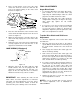
4. Place one flat washer on the end of the chute crank, then insert the end of the crank into the hole in the plastic bushing in the chute crank bracket. See Figure 17. Flat Washer Chute Crank FINAL ADJUSTMENTS Auger Drive Clutch 1. To check the adjustment of the auger drive clutch, push forward on the left hand clutch grip depressing the rubber bumper under the clutch grip. There should be slack in the cable. 2. Release the clutch grip. The cable should be straight.
Adjusting The Skid Shoes The space between the shave plate and the ground can be adjusted by adjusting the skid shoes. 1. Place skid shoes in the low position to remove snow close to the ground. Place skid shoes in a higher position to remove snow from uneven ground. See Figure 19. 2. Adjust skid shoes by loosening the four hex nuts and carriage bolts and moving skid shoes to desired position. Make certain the entire bottom surface of skid shoe is against the ground to avoid uneven wear on the skid shoes.
Auger Drive Clutch Auger Drive Clutch Traction Drive Clutch Shift Lever Chute Crank Traction Drive Clutch Shift Lever Chute Crank Models 642 and 662 Models 614, 644, 664, and 6A4 Figure 22 Figure 23 SECTION 7: OPERATION BEFORE STARTING WARNING: Observe all Warning Labels Metal Loop on Spark Plug Wire on the snow thrower prior to use. See Figure 1. Rubber Boot Your snow thrower is shipped with oil; however, you must check the oil level before operating. Be careful not to overfill.
4. Push primer button two or three times. Refer to Figure 21. If engine is warm, push primer button once only. Follow all instructions carefully. Determine that your house wiring is a three wire grounded system. Ask a licensed electrician if you are not certain. If your house wiring system is not a three-wire grounded system, do not use this electric starter under any conditions.
TO ENGAGE DRIVE/AUGER WARNING: Temperature of muffler and surrounding areas may exceed 150oF. Avoid these areas. 1. With the engine running near top speed, move shift lever into one of the FORWARD or REVERSE positions. Select a speed appropriate for the snow conditions that exist. Use the slower speeds until you are familiar with the operation of the snow thrower. • For most efficient snow removal, remove snow immediately after it falls. • Discharge snow downwind whenever possible.
Models 614, 644, 664, and 6A4: 5. If adjustment is necessary, loosen the jam nut on the traction drive cable, and thread cable in or out as necessary. 3. Push down on the shift arm assembly as far as it will go. Thread the ferrule up or down the shift rod and align it with the hole closest to the shift knob on the narrow side of the shift lever assembly behind the handle panel. 6. Tighten the jam nut to secure the cable when correct adjustment is reached.
SECTION 9: LUBRICATION WARNING: Disconnect the spark plug wire and ground against the engine before performing any lubrication or maintenance. GEAR CASE The gear case is lubricated with grease at the factory and does not require checking. If disassembled for any reason, lubricate with 2 ounces of shell grease, part number 737-0168. ENGINE Refer to engine manual for all engine lubrication instructions. IMPORTANT: Do not overfill the gear case. Damage to the seals could result.
AUGER BELTS 5. Roll the front and rear auger belts off the engine pulley. See Figure 30. NOTE: It is necessary to remove both belts in 6. Unhook the idler spring from the hex bolt on the auger housing. See Figure 31. order to change either one. If changing just one belt, be certain to check the condition of the other belt. 7. Back out the stop bolt to allow the belts to slip between the bolt and auger pulley. See Figure 32. 1.
Friction Wheel Disc 6. Lightly tap the hex nut to dislodge the ball bearing from the right side of frame. Remove the hex nut and bell washer from left end of shaft. Friction Wheel 7. Slide the gear shaft to the right and slide the friction wheel assembly from the shaft. Drive Belt 8. Remove the six screws from the friction wheel assembly (three from each side). Remove the friction wheel rubber from between the friction wheel plates. Support Bracket 9.
SECTION 12: TROUBLE SHOOTING GUIDE Trouble Possible Cause(s) Corrective Action Engine fails to start Fuel tank empty, or stale fuel. Fill tank with clean, fresh gasoline. Fuel will not last over thirty days unless a fuel stabilizer is used. Clean fuel line. Blocked fuel line. Move switch to ON position Choke not in ON position Clean, adjust gap or replace. Faulty spark plug. Key not in switch on engine. Insert key. Connect spark plug wire. Spark plug wire disconnected. Primer button not depressed.
Gear Assembly All Models 9 1 12 5 8 13 6 10 17 16 15 14 3 4 7 2 REF. NO. 1 2 3 4 5 6 7 8 PART NO. 618-0123 618-0124 710-0642 711-0908 711-0909 711-0910 714-0161 715-0143 717-0526 717-0528 718-0186 11 REF. NO. 9 10 11 12 13 14 15 16 17 DESCRIPTION Housing—L.H. Housing—R.H. Hex Screw 1/4-20 x .75 Spiral Axle 24" Spiral Axle 26" Spiral Axle 28" Key Pin-Spiral Shaft-Worm Gear-Worm Collar-Thrust 20 PART NO.
Blower Housing All Models 8 7 6 9 5 10 38 11 3 12 9 2 1 4 14 21 13 7 6 16 20 8 15 18 29 30 31 32 7 34 13 19 18 22 23 37 26 33 24 13 33 6 28 36 16 27 37 32 6 7 33 25 33 31 32 30 6 35 36 21 32 17 16
Blower Housing REF. NO. 1 2 3 4 5 6 7 8 9 10 11 12 13 14 15 16 17 18 19 20 21 22 PART NO. 712-0116 756-0178 784-5632 710-0459A 741-0475 736-0242 712-3010 712-0324 736-0463 705-5226 731-1379 710-0134 710-0451 738-0281 736-0174 712-3068 732-0611 736-0119 05931 741-0309 684-0039B 684-0040B 684-0041B 736-0169 DESCRIPTION Lock Jam Nut 3/8-24 Flat Idler Auger Idler Arm Hex Cap Screw 3/8-24 x 1.
Handle Assembly All Models 17 16 18 17 20 2 1 8 16 3 4 5 19 22 27 26 20 6 25 18 23 9 19 28 10 7 11 24 21 29 13 12 30 38 14 39 31 22 40 15 6 32 24 23 7 41 23 33 39 42 35 43 23 34 44 7 29 36 47 45 37 46 51 50 48 49 52 23
Handle Assembly REF. NO. 1 2 3 4 5 6 7 8 9 10 11 12 13 14 15 16 17 18 19 20 21 22 23 24 25 26 PART NO.
Frame Assembly All Models 27 20 37 39 Drive Clutch Cable 20 5 13 7 38 1 11 6 10 37 Auger Clutch Cable 4 3 40 4 1 2 14 15 26 5 36 16 16” Wheels 25 13” or 15” Wheels 7 31 28 23 10 12 17 21 18 24 32 9 11 25 8 4 1 22 33 1 20 29 8 5 34 19 26 35 Blower Housing 30 1 25 1 Auger Clutch Cable
Frame Assembly REF. NO. 1 2 3 4 5 6 7 8 9 10 11 12 13 14 15 16 17 18 19 20 21 PART NO. 710-1652 784-5688 784-5687 756-0625 738-0924 684-0030 741-0563 736-0105 712-0116 741-0598 736-0188 784-5689A 710-0538 736-0242 714-0474 736-0160 710-0788 784-5590 784-5638 710-0599 736-0351 REF. NO.
Engine and V-Belts IMPORTANT: For a proper working machine, use Factory Approved Parts. V-BELTS are specially designed to engage and disengage safely. A substitute (non OEM) V-Belt can be dangerous by not disengaging completely. 614E 1 2 3 5 4 8 9 11 13 10 12 27 15 16 20 22 4 16 7 6 23 14 24 18 17 19 25 REF. NO. 1 2 3 4 5 6 7 8 9 10 11 12 13 14 PART NO.
Engine and V-Belts IMPORTANT: For a proper working machine, use Factory Approved Parts. V-BELTS are specially designed to engage and disengage safely. A substitute (non OEM) V-Belt can be dangerous by not disengaging completely. E642E, E644E, E664F 1 2 3 4 7 13 12 10 5 8 14 22 16 23 6 15 22 9 23 10 24 11 25 17 26 18 19 20 27 21 21 REF. NO. 1 2 3 4 5 6 7 8 9 10 11 12 13 14 PART NO.
Engine and V-Belts E6A4E, E662H 1 2 26 4 3 5 9 8 10 21 20 12 11 20 21 5 20 7 6 22 23 14 13 24 16 25 18 19 REF. NO. 1 2 3 4 5 6 7 8 9 10 11 12 13 PART NO. 710-0599 731-1324 710-3005 732-0710 710-0627 05896A 748-0234 756-0987 754-0430 756-0986 736-0270 710-0230 756-0313 IMPORTANT: For a proper working machine, use Factory Approved Parts. V-BELTS are specially designed to engage and disengage safely. A substitute (non OEM) V-Belt can be dangerous by not disengaging completely.
MANUFACTURER’S LIMITED WARRANTY For TWO YEARS from the date of retail purchase within the United States of America, its possessions and territories, the manufacturer will, at its option, repair or replace, for the original purchaser, free of charge, any part or parts found to be defective in material or workmanship.