IMC-21GA Quick Installation Guide Moxa Industrial Media Converter Edition 4.0, June 2017 Technical Support Contact Information www.moxa.
Overview The IMC-21GA Series includes industrial 10/100/1000BaseT(X) to 100/1000BaseFX media converters that provide a cost-effective solution, and are specially designed for a reliable and stable operation in industrial environments. Package Checklist Moxa’s IMC-21GA is shipped with the following items. If any of these items are missing or damaged, please contact your customer service representative for assistance.
Panel Layout 1. 2. 3. 4. 5. 6. 7. 8. 9.
Mounting Dimensions DIN-Rail Mounting The aluminum DIN-rail attachment plate should be fixed to the back panel of the IMC-21GA when you take it out of the box. If you need to reattach the DIN-rail attachment plate to the IMC-21GA, make sure the stiff metal spring is situated towards the top. Wiring Requirements ATTENTION Safety First! Be sure to disconnect the power cord before installing and/or wiring your IMC-21GA. Calculate the maximum possible current allowed in each power wire and common wire.
• • • • • Use separate paths to route the wiring for power and devices. If the power wiring and device wiring must cross paths, make sure the wires are perpendicular at the intersection point. Do not run signal or communications wires and power wires in the same wire conduit. To avoid interference, wires with different signal characteristics should be routed separately. You can use the type of signal transmitted through a wire to determine which wires should be kept separate.
Redundant Power Inputs Both power inputs can be connected simultaneously to live DC power sources. If one power source fails, the other live source acts as a backup, and automatically supplies all of the IMC-21GA’s power needs. Communication Connections RJ45 Ethernet Port Connection The IMC-21GA has one 10/100/1000BaseT(X) Ethernet port located on the front panel to connect Ethernet-enabled devices.
1000BaseT(X) Ethernet Port Connection 1000BaseT(X) data is transmitted on differential TRD+/- signal pairs over copper wires.
1000BaseSX/LX Fiber Port (IMC-21GA-SX-SC, IMC-21GA-LX-SC) The concept behind the SC port and cable is straightforward. Suppose you are connecting devices I and II: contrary to electrical signals, optical signals do not require a circuit in order to transmit data. Consequently, one of the optical lines is used to transmit data from device I to device II, and the other optical line is used to transmit data from device II to device I, for full-duplex transmission.
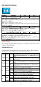
DIP Switch Settings Dip No.
LED Color State Description Blinking Data is being transmitted at 100 Mbps Off Fiber port’s 100 Mbps link is inactive LFP: DIP switch is set to LFP mode TP1 Faulted F1 Faulted F2 Faulted TP2 Faulted DUTA TP DUTB TP Device1 DUTA FO DUTB FO Device 2 LNK (G1) LNK (G1) TP LED (G2) LED (G2) LED TP LED LED LED OFF OFF OFF OFF OFF OFF OFF OFF OFF OFF OFF OFF OFF OFF OFF OFF OFF OFF OFF OFF OFF OFF OFF OFF LFP: DIP switch is set to DIS mode TP1 Faulted F1 Faulted F2 Faulted TP2 Faulted DUTA TP DUTB TP Devic
Auto-Negotiation and Speed Sensing All of the IMC-21GA’s RJ45 Ethernet ports independently support auto-negotiation for transmission speeds of 10 Mbps, 100 Mbps , and 1000 Mbps in operations according to the IEEE 802.3u standard. This means that some nodes could be operating at 10 Mbps, while at the same time, other nodes are operating at 100 Mbps or 1000 Mbps. Auto-negotiation takes place when an RJ45 cable connection is made, and then each time a LINK is enabled.
Environmental Limits Operating Standard models: -10 to 60°C (14 to 140°F) Temperature Wide temp.