
Service Manual


55
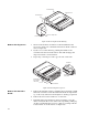
Assembly of Front Cover
to Main Chassis
Refer to exploded views on page 88 for parts referenced in this
procedure.
1. Install the 18 pin connector into the female connector (mounted
on the PC board) through the hole in the front of the chassis.
2. Place white remote retainer (4205395X01) over the 18 pin
connector.
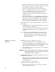
Figure 29. VRS750 Torque Sequence
Table 8. VRS750 Torque Sequence
Step No. Screw P/N Bit Torque Notes
1 6 0310907A20 Torx T10 — Start Only
2 — — — Place Antenna Conn.
3 4-8 0310907A20 Torx T10 8 in-lb Number 6 Inclusive
4 1-3 0310907A20 Torx T10 8 in-lb
Figure 30. Cover Gasket Location
4
2
7
8
5
3
1
6
Cover gasket
Twist o-ring