
User's Manual


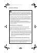


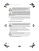
Table Of Contents
- APX Vehicular Adapter (VA) System Compatibility Matrix
- ASTRO™ APX™ Vehicular Adapter (APX VA) RF Energy Exposure and Product Safety
- RF Energy Exposure Awareness and Control Information, and Operational Instructions for Federal Communication Commission (FCC) Occupational Use Requirements
- Federal Communication Commission (FCC) Regulations
- Compliance with RF Exposure Standard
- RF Exposure Compliance and Control Guidelines and Operating Instructions
- Mobile Antenna Installation Guidelines
- Approved Accessories
- Additional Information
- Compliance and Control Guidelines and Operating Instructions for Mobile Two-Way Radios Installed as Fixed Site Control Stations
- Compliance and Control Guidelines and Operating Instructions for Mobile Two-Way Radios Installed on Maritime Vessels
- Electromagnetic Interference or Compatibility
- Driver Safety
- Acoustic Safety
- Operational Warnings
- Installation Instructions
- Introduction
- Installation Requirements for Compliance with RF Energy Exposure Safety Standards
- Installation Planning
- Console Installation
- Antenna Installation
- Console Cabling
- LED Surveillance Configuration (Option Wiring – User Configurable)
- Installation Verification
- Maintenance
- Operational Warnings
- Operational Cautions
- Efficient System Operation
- User Guide

20
Console Cabling
Refer to Figure 5 and Figure 6 before routing or connecting any console cable.
The console should be cabled using the following procedure:
Note: 1. Due to space restrictions, it may be necessary to remove the console
before making connections to the connectors at the back of the
console. If this is the case, make all connections and remount the
console before replacing the 5-amp fuses.
2. For applications where the mounting structure of the console is
hinged (for example, swing cab), make sure to provide sufficient
service length for cables.
1. After setting the 2-foot (61 cm) section of the main power cable’s red lead
aside for later use, route the main power cable through the firewall and
into the vehicle battery area. Use an existing opening or, if necessary, drill
a 3/8-inch (1 cm) hole through the firewall. Insert a grommet (not
provided) into the hole to prevent damage to the power cable.
Figure 5: Console Connections
• This product is designed for a 12-volt, negative-ground
system.
• Remove the 5-amp fuses from the power cable (red and
yellow wires) before proceeding.
Microphone Connector (J4)
Antenna Connector (J3)
Speaker and
Interface
Connector (J1)
Supply
Connector (J2)
MN000350A02.book Page 20 Tuesday, December 2, 2014 3:01 PM