
Service Manual

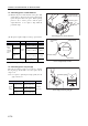
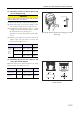


Table Of Contents
- BINDING
- INTRODUCTION
- How to use this manual
- Safety Cautions
- Fire and explosion
- Stay clear of all rotating and moving parts
- Be careful of burns
- Be careful of exhaust fume poisoning
- Protect ears from noises
- Be careful of falling down
- Be careful of handling fuel, engine oil and LLC
- Service battery
- When abnormality occurs
- Other cautions
- Modification of engine prohibited
- Never break the seals
- Pre-operational check and periodic inspection/maintenance
- Break-in operation
- Warming-up operation
- Avoid engine operations in a overload condition
- Cooling operation before stopping engine
- Protection of engine against water entry
- Maintenance of air cleaner or pre-cleaner
- Observe safety rules at work site
- Work clothing and protective gear
- Use of tools optimum for each work
- Avoidance of prolonged time of starter operation
- Do not turn off battery switch during operation
- Cautionary instructions for transporting engine
- Avoid continuous engine operation in a low load condition
- Ventilation of engine room
- Avoid contact with high-pressured fuel
- About warning labels
- GENERAL CONTENTS
- GENERAL
- SERVICE DATA
- SERVICE TOOLS
- DETERMINATION OF OVERHAUL
- DISASSEMBLY OF BASIC ENGINE
- 1. Disassembling and inspecting cylinder head and valve mechanism
- 2. Disassembling and inspecting flywheel
- 3. Disassembling and inspecting damper, gear case, timing gear and camshaft
- 3.1 Removing crankshaft pulley and damper
- 3.2 Removing cover
- 3.3 Removing timing gear case
- 3.4 Measuring timing gear backlash
- 3.5 Measuring idler gear and camshaft gear end play
- 3.6 Removing fuel injection pump
- 3.7 Removing oil pan
- 3.8 Removing oil strainer
- 3.9 Removing oil pump gear
- 3.10 Removing idler gear
- 3.11 Removing PTO drive gear
- 3.12 Removing camshaft
- 3.13 Separating camshaft gear
- 3.14 Installing camshaft gear and thrust plate
- 3.15 Removing front plate
- 3.16 Removing oil pump
- 4. Disassembling and inspecting piston, connecting rod, crankshaft and crankcase
- INSPECTION AND REPAIR OF BASIC ENGINE
- 1. Inspecting and repairing cylinder head and valve mechanism
- 1.1 Measuring clearance between rocker bushing and rocker shaft
- 1.2 Measuring valve stem outside diameter and valve guide inside diameter
- 1.3 Replacing valve guide
- 1.4 Inspecting valve face
- 1.5 Refacing valve face
- 1.6 Refacing valve seat
- 1.7 Replacing valve seat
- 1.8 Lapping valve and valve seat
- 1.9 Measuring perpendicularity and free length of valve spring
- 1.10 Measuring distortion of the bottom surface of the cylinder head
- 1.11 Measuring push rod runout
- 1.12 Removing combustion jet
- 2. Inspecting and repairing flywheel
- 3. Inspecting and repairing timing gear and camshaft
- 3.1 Measuring timing gear backlash
- 3.2 Measuring idler gear and camshaft gear end play
- 3.3 Measuring cam lift
- 3.4 Measuring camshaft runout
- 3.5 Measuring camshaft journal outside diameter
- 3.6 Measuring camshaft bushing inside diameter
- 3.7 Replacing camshaft bushing
- 3.8 Measuring idler bushing inside diameter and idler shaft outside diameter
- 3.9 Replacing idler shaft
- 3.10 Measuring clearance between tappet and tappet guide hole
- 3.11 Inspecting tappet
- 3.12 Inspecting V-belt groove wear
- 3.13 Inspecting damper
- 4. Inspecting and repairing piston, connecting rod, crankshaft and crankcase
- 4.1 Measuring crankcase top surface distortion
- 4.2 Measuring cylinder inside diameter
- 4.3 Measuring piston outside diameter
- 4.4 Measuring piston ring end gap
- 4.5 Measuring clearance between piston ring groove and piston ring
- 4.6 Measuring piston pin bore diameter and piston pin outside diameter
- 4.7 Measuring piston protrusion
- 4.8 Measuring clearance between connecting rod bearing and crankpin
- 4.9 Measuring clearance between connecting rod bushing and piston pin
- 4.10 Replacing connecting rod bushing
- 4.11 Inspecting connecting rod bend and twist
- 4.12 Inspecting connecting rod bearing
- 4.13 Measuring connecting rod end play
- 4.14 Weight difference of connecting rod assembly in one engine
- 4.15 Measuring crankshaft journal outside diameter
- 4.16 Measuring crankshaft crankpin outside diameter
- 4.17 Grinding crankshaft
- 4.18 Measuring crankshaft end play
- 4.19 Measuring crankshaft runout
- 4.20 Replacing crankshaft gear
- 4.21 Inspecting oil seal contact surface
- 4.22 Installing oil seal sleeve
- 4.23 Removing oil seal sleeve
- 4.24 Inspecting main bearing surface
- 4.25 Measuring clearance between main bearing and crankshaft journal
- 1. Inspecting and repairing cylinder head and valve mechanism
- REASSEMBLY OF BASIC ENGINE
- 1. Reassembling piston, connecting rod, crankshaft and crankcase
- 1.1 Installing main bearing
- 1.2 Installing thrust plate
- 1.3 Installing tappet
- 1.4 Installing crankshaft
- 1.5 Installing main bearing caps
- 1.6 Inserting side seal
- 1.7 Installing main bearing cap bolt
- 1.8 Measuring crankshaft end play
- 1.9 Reassembling piston and connecting rod
- 1.10 Installing piston ring
- 1.11 Preparation for installing pistons
- 1.12 Installing connecting rod bolt and connecting rod bearing
- 1.13 Installing pistons
- 1.14 Installing connecting rod cap
- 2. Reassembling timing gear and camshaft
- 2.1 Installing oil pump
- 2.2 Installing front plate
- 2.3 Installing camshaft gear and thrust plate
- 2.4 Installing camshaft
- 2.5 Installing PTO drive gear
- 2.6 Installing idler gear
- 2.7 Installing oil pump gear
- 2.8 Installing fuel injection pump
- 2.9 Inspecting and adjusting timing gear after installation
- 2.10 Installing front oil seal
- 2.11 Installing timing gear case
- 2.12 Installing oil strainer
- 2.13 Installing oil pan
- 2.14 Installing cover
- 2.15 Installing crankshaft pulley and damper
- 3. Reassembling flywheel
- 4. Reassembling cylinder head and valve mechanism
- 4.1 Cleaning cylinder head bottom surface
- 4.2 Installing valve stem seal
- 4.3 Installing valve and valve spring
- 4.4 Installing cylinder head gasket
- 4.5 Installing cylinder head assembly
- 4.6 Tightening cylinder head bolts
- 4.7 Inserting push rod
- 4.8 Reassembling rocker shaft assembly
- 4.9 Installing rocker shaft assembly
- 4.10 Determining top dead center of No. 1 cylinder compression stroke
- 4.11 Adjusting valve clearance
- 4.12 Installing rocker cover
- 1. Reassembling piston, connecting rod, crankshaft and crankcase
- FUEL SYSTEM
- 1. Removing fuel system
- 2. Disassembling, inspecting and reassembling fuel system
- 2.1 Disassembling and inspecting fuel filter
- 2.2 Changing fuel filter
- 2.3 Disassembling and inspecting fuel injection nozzle
- 2.4 Inspecting and adjusting fuel injection valve opening pressure
- 2.5 Inspecting fuel spray pattern of fuel injection nozzle
- 2.6 Cleaning and inspecting nozzle tip
- 2.7 Reassembling fuel injection nozzle
- 2.8 Inspecting and cleaning gauze filter of distribute type fuel injection pump
- 3. Installing fuel system
- LUBRICATION SYSTEM
- 1. Removing lubrication system
- 2. Disassembling, inspecting and reassembling lubrication system
- 2.1 Disassembling and inspecting oil pump
- 2.2 Inspecting oil pump
- 2.2.1 Measuring clearance between outer rotor and inner rotor
- 2.2.2 Measuring end play of rotor and pump case
- 2.2.3 Measuring clearance between outer rotor and pump case
- 2.2.4 Measuring clearance between main shaft and pump case
- 2.2.5 Measuring clearance between main shaft and bushing
- 2.2.6 Installing oil pump bushing
- 2.3 Reassembling oil pump
- 2.4 Disassembling and inspecting oil cooler
- 2.5 Inspecting oil filter
- 2.6 Inspecting relief valve
- 2.7 Inspecting safety valve
- 3. Installing lubrication system
- COOLING SYSTEM
- INLET AND EXHAUST SYSTEMS
- ELECTRICAL SYSTEM
- 1. Removing electrical system
- 2. Disassembling, inspecting and reassembling electrical system
- 2.1 Inspection before disassembling starter
- 2.2 Disassembling and inspecting starter
- 2.3 Inspecting and repairing starter
- 2.3.1 Inspecting brushes for wear
- 2.3.2 Measuring brush spring load
- 2.3.3 Inspecting brush holder for insulation
- 2.3.4 Measuring commutator radial runout
- 2.3.5 Measuring commutator outside diameter
- 2.3.6 Measuring undercut depth
- 2.3.7 Checking armature coil
- 2.3.8 Inspecting field coil
- 2.3.9 Inspecting rear bracket
- 2.3.10 Inspecting overrunning clutch operation
- 2.3.11 Inspecting front bracket
- 2.3.12 Inspecting gears of starter
- 2.3.13 Inspecting magnetic switch
- 2.3.14 Inspecting starter relay
- 2.4 Reassembling starter
- 2.5 Disassembling and inspecting alternator
- 2.6 Inspecting and repairing alternator
- 2.7 Reassembling alternator
- 2.8 Inspecting glow plug
- 2.9 Inspecting magnetic valve (stop solenoid)
- 2.10 Installing magnetic valve (stop solenoid)
- 3. Installing electrical system
- ADJUSTMENT AND OPERATION
- 1. Adjusting engine
- 2. Break-in operation
- 3. Performance test (JIS standard)

INSPECTION AND REPAIR OF BASIC ENGINE
6-21
4.8 Measuring clearance between connecting
rod bearing and crankpin
CAUTION
When grinding crankpins, be sure to grind all the pins
to the same size.
Finish the fillet radius to the specified dimension.
(1) Reassemble the bearing into the big end of the
connecting rod.
(2) Tighten the connecting rod cap bolts to the specified
torque.
(3) Measure the inside diameter of the connecting rod
bearing.
(4) Measure the outside diameter of the crankpin.
(5) Calculate the clearance from the difference between the
inside diameter of the connecting rod bearing and
outside diameter of the crankpin.
(6) Replace the connecting rod bearing if the clearance
exceeds the limit.
(7) Measure the clearance between the connecting rod
bearing and the crankpin again. Use the undersize
bearing if the limit is exceeded.
(8) If an undersize bearing is used, grind the crankpin to
the specified undersize.
Measuring connecting rod bearing inside diameter
Measuring crankpin diameter
4.9 Measuring clearance between connecting
rod bushing and piston pin
Measure the inside diameter of the connecting rod bushing
and the outside diameter of the piston pin. Replace if the
limit is exceeded.
Measuring connecting rod bushing inside diameter
Item Nominal Standard Limit
Crankpin
outside diameter
ø 58 mm
[2.28 in.]
57.955 to 57.970 mm
[2.2817 to 2.2823 in.]
57.800 mm
[2.2756 in.]
Clearance between
crankpin and
connecting rod bearing
(oil clearance)
-
0.030 to 0.090 mm
[0.0012 to 0.0035 in.]
0.200 mm
[0.0079 in.]
Measuring
directions
Measuring
points
54 ± 5 N·m
{5.5 ± 0.5 kgf·m}
[40 ± 3.6 lbf·ft]
Measuring
directions
Measuring
points
Item Nominal Standard Limit
Bushing
inside diameter
ø 30 mm
[1.18 in.]
30.020 to 30.045 mm
[1.1819 to 1.1829 in.]
-
Clearance between
connecting rod
bushing
-
0.020 to 0.091 mm
[0.0008 to 0.0036 in.]
0.120 mm
[0.0047 in.]
Measuring
directions
Measuring
points