
Operating instructions


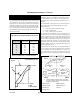


Cutting Compound Miters (Fig. 23 & 24)
Fig. 23 identifies miter and bevel settings for various types of
crown molding for 90° corners. Note that these are-ideal set-
tings and may vary because many moldings have slightly dif-
ferent spring angles and some walls are not perfectly square.
If the wall or ceiling is bumpy, the miter angle will not hold
true, so the bumps may need to be sanded. Fig. 24 illustrates
the relationship between the spring angle, the ceiling, the
wall and the molding.
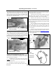
Positioning Crown Molding on The Saw (Fig. 25 & 26)
Determining how to lay a workpiece on the miter saw table
for cutting molding can be tricky for even the experienced
woodworker. Figs. 25 & 26 and these instructions serve as a
guideline.
The wood labeled A, B, C & D in Fig. 25 are the four pieces
of wood that form an inside and an outside corner. Each
piece of wood has:
z a “top” edge, which is against the ceiling
z a “left” or “right” name
z a “face,” which is the visible surface
Fig. 26 illustrates three different views of wood pieces A, B,
C & D. Wood A1, 131, C1 & D1 shows the wood lying flat on
a table. Dashed lines on the wood pieces indicate that the
bevel is “hidden”, meaning it is on the underside of the wood.
When the inside corner woods Al and 131 are lying flat on a
table, the bevel faces are exposed (i.e. on top). However, when
the outside corner woods C1 and D1 are lying flat on a table,
they have “hidden” bevel faces, meaning the bevel angle is on
the underside of the. wood.
Wood pieces A2, A3, B2, B3, C2, C3, D2 and D3 illustrate A,
B, C, & D lying on the miter saw table both face up and face
down as indicated. Using these illustrations as a guide, it is
easy to determine how to lay the wood against the miter saw
fence and how to set the miter and bevel angle for a compound
cut.
Operating Instructions (continued)
Page 8
RenTrain INC
RenTrain INC
Fig 23.
Angle Settings for Compound Saw (for 90
0
corner)
Wood is positioned flat on the miter saw table.
Type of Crown
(spring angle)
Miter
(angle of table)
Miter
(angle of blade)
30
0
35
0
38
0
40
0
45
0
52
0
26.6
0
29.8
0
31.6
0
32.7
0
35.3
0
38.2
0
37.8
0
35.4
0
33.9
0
32.8
0
30.0
0
25.8
0
Crown Molding Profile
1. Ceiling
2. Wall
3. Spring Angle
Fig. 24
1.
2.
3
Applications
z These workpieces are Face Down. Face down
cuts can be used in special cases, depending on
the type of crown molding.
Fig. 25
Inside Corner
Outside Corner
Top
Left Face
Top
Left Face
Top
Left Face
Face Up
Face Up
Top
Left Face
Top
Left Face
Top
Left Face
Top
Right Face
Top
Right Face
Top
Right Face
Blade Kerf
Here
Blade Kerf
Here
Top
Right Face
Top
Right Face
Top
Right Face
Top
Left Face
A1
B2
A2 A3
D1
C3
D3
D2
C2
Top
Right Face
B3
Top
Left Face
C1
Top
Right Face
B1
*
*
*
*
Miter Saw Fence
Miter Saw Fence
Miter Saw Fence
Miter Saw Fence
Inside Corner
Outside Corner
Top left face
Top right face
Blade kerf here
Miter saw fence
Face up