
Operation Manual


74 Chapter 8: Patching
PRO Series Live Audio Systems
Owner’s Manual
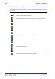
What the Patching screen symbols mean
The following table gives a description of all the symbols that appear on the Patching
screen tabs.
Symbol Description
During patching, this triangle appears under a tab name when the tab
contains a selected patch connector.
Shown at the top of the channel patch connectors, this box aids channel
identification by matching the user-configured colour for that channel.
Insert return patch connector.
Insert send patch connector.
Bus or channel source patch connector.
Bus or channel destination patch connector.
Female XLR chassis patch connector (input).
Male XLR chassis patch connector (output).
Jack patch connector.
Non-functional patch connector, that is, one that cannot be patched.
Compressor sidechain input patch connector.
Gate input patch connector.
DN9696 recorder patch connector.
Set-up button, which opens the device configuration window (see
“Configuring the devices” on page 89 for details).