
User Manual Part 1


Notices Notices-iiiMTX5000 User and Technical Manual
User Input
RF power delivered to the antenna = Watts
Antenna gain (referenced to isotropic antenna) = dBi
Distance from the center of radiation = Feet
Calculation steps:
1. [P] RF power input. Convert watts to milliwatts = Watts *
1000
2. [G] Antenna gain dBi. Convert to numeric gain = Antilog
(dBi/10)
3. [EIRP] Multiply P * G
4. [R] Convert centimeters to feet = Centimeters * .0328
5. Square R
6. Multiply R² * 4π
7. [S] Divide (R² * 4π) into EIRP
S = Power Density in milliwatts per square centimeters. Note:
At frequencies above 1500 MHz, S must not be greater than 1.
Reference
FCC OET Bulletin 65, August 1997 - Evaluating Compliance with
FCC Guidelines for Human Exposure to Radio Frequency
Electromagnetic Fields
The examples shown in Figure 1 and Figure 2 are typical graphs
for an MRC STRATA Transmitter and show the permissible
exposure distance for various antennas. Graphs and data will
vary, based on the actual transmitter, output power, frequency,
and antenna utilized. One plot provides the permissible output
of the transmitter for digital modulation, and the other plot for
analog modulation.
MRC, in accordance with the requirements set forth by the FCC,
provides this information as a guide to the user. It is assumed
that the users of this equipment are licensed and qualified to
operate the equipment per the guidelines and recommendations
contained within the product user guides and in accordance with
any FCC rules that may apply.
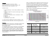
Figure 1 with its corresponding table shows the 2GHz MPE.
Figure 1: MTX5000 MPE 2GHz
Antenna
Gain (dBi)
Minimum Dis-
tance from
Antenna (cm)
Minimum Distance
from Antenna (inch)
0 28 11.02
5 50 19.68
16 177 69.67
20 279 109.81
35 1569 617.56