
Specifications


Source Organization:
::
:
USI CVS2/RD2/NS
DOC NO.:
Original Effective Date:
::
:
01-09-2014
AP832e / AP832i /AP822e /AP822i
Hardware
Specification
PAGE
7 OF 10
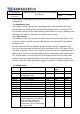
GPIO_13 Hard reset Ethernet PHY2 and
PHY1, connecting to PHY2’s
Hardware Reset pin after ORing
with Power-On-Reset#, PHY2 is
connected to CPU’s SGMII2 and
support PoE
Output High Low
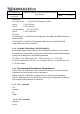
3.3.9 IRQ Definitions
IRQs Description
IRQ00 reserved
IRQ01 IRQ for TSEC3’s PHY
IRQ02 IRQ for TSEC1’s PHY
IRQ03 reserved
IRQ04 reserved
IRQ05 reserved
IRQ06 reserved
3.3.10 UART
• One UART RS-232 console port support phone jack and pin header link. A 3.3V
RS-232 transceiver will be used.
3.3.11 JTAG
• To connect ICE debuggers, a JTAG connector must be provided internal to the
enclosure and should be a stuff option when in MP production.
3.3.12 PCIE INTERFACE
• The hardware design must provide two miniPCIe interfaces which capable of
supporting full size miniPCIe card.
3.3.13 USB INTERFACE
• The hardware design must provide one USB Host port with shielded vertical-mount
standard type-A USB receptacle connector. The port should supply current up to
500mA at 5V nominal as per USB2.0 specification
3.3.14 POWER SUPPLY
• Support POE/DC adapter supply, internal DC/DC generates 12V, 5V, 3.3V, 1.0V, 1.5V
and 0.75V voltage for chip used.
3.3.15 POWER REQUIREMENT
• The PoE must comply with 802.3at and electrically isolate from the AP chassis. The
maximum load on PoE input must be no more than 18W for the full system in the