
User manual


DataFW4 / DATAREG
User Manual
Page 29
Bär Industrie-Elektronik GmbH ⋅ Rathsbergstr. 23 ⋅ D-90411 Nürnberg ⋅ Phone 0911/970590 ⋅ Fax +49 911 9705950
2.1 Keyboard with LCD display
1
2
3
4
8
9
10
11
12
5 6 7
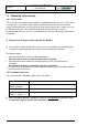
Figure 4,
Keyboard
1: LED A1 (red, blinking):
an error has occurred (warning)
2: LED A2 (red, blinking):
an error has occurred (critical error)
3: LED M (green, blinking):
measuring will soon begin
LED M (green, lit):
measuring is active
4: RS232 (V.24) service interface
5: ENTER:
Accepts an entry (exception: error inquiry)
6: Numbers:
For entering numeric values when setting
parameters.
7: EXIT: Leaves a menu item
Note: If you press the EXIT key several times you will be returned to the permanent
display.
8: Cursor : Pages through individual (next) menu items
Activate the main menu
9: Cursor : Positions the cursor in numeric entry fields (to the right), or it is used for selecting
table values
10: Cursor : Positions the cursor in numeric entry fields (to the left), or it is used for selecting
table values
11: Cursor : Pages through individual (prior) menu items
12: Display: 2x16 characters
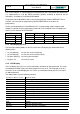
2.1.1 RS232 (V.24) service interface
Type: 25 pole SUB-D plug in compliance with ISO 2110, Connector pin
assignment V.24 / RS232/DIN 66020
Socket function: Parameterization and read-out of the reset data through a PC.
The pin assignment of the V.24 socket on the CPU front panel is as follows:
Connection Designation
Additional information
2 TxD Input Receive data
3 RxD Output Transmit data
4 RTS Input
Connected to 5
5 CTS Output Connected to 4
6 DSR Output Operational
7 GND Signal ground
20 DTR Input DEE Operational