
Datasheet


����������������������������������������������������������������� Maxim Integrated Products 5
MAX174/MX574A/MX674A
Industry-Standard, Complete 12-Bit ADCs
Note 1: Adjustable to zero.
Note 2: With 50ω fixed resistor from REFOUT to BIPOFF. Adjustable to zero.
Note 3: With 50ω fixed resistor from REFOUT to REFIN. Adjustable to zero.
Note 4: Maximum change in specification from T
A
= +25°C to T
MIN
or T
A
= +25°C to T
MAX
.
Note 5: External load current should not change during a conversion. For Q12V supply operation, REFOUT need not be buffered
except when external load in addition to REFIN and BIPOFF inputs have to be driven.
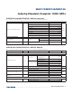
ELECTRICAL CHARACTERISTICS—MAX174/MX574/MX674A (continued)
(V
L
= +5V, V
CC
= +15V or +12V, V
EE
= -15V or -12V, T
A
= +25NC, unless otherwise noted.)
PARAMETER SYMBOL CONDITIONS MIN TYP MAX UNITS
Input Current I
IN
CS, CE, R/C, A0, 12/8, V
IN
= 0 to V
L
±5 µA
Input Capacitance C
IN
CS, CE, R/C, A0, 12/8
7 pF
LOGIC OUTPUTS
Output Low Voltage V
OL
DB11–DB0, STS I
SINK
= 1.6mA 0.4 V
Output High Voltage V
OH
DB11–DB0, STS I
SOURCE
= 500µA 4 V
Floating State Leakage Current I
LKG
DB11–DB0, STS V
OUT
= 0 to V
L
±10 µA
Floating State Output Capacitance C
OUT
DB11–DB0 8 pF
CONVERSION TIME
12-Bit Cycle t
CONV
MX574A 15 20 25
µsMX674A 9 12 15
MAX174 6 7 8
8-Bit Cycle t
CONV
MX574A 10 14 18
µsMX674A 6 8 11
MAX174 4 5 6
POWER REQUIREMENTS
V
CC
Operating Range 11.4 16.5 V
V
L
Operating Range 4.5 5.5 V
V
EE
Operating Range -11.4 -16.5 V
V
CC
Supply Current (Note 5) I
CC
3 5 mA
V
L
Supply Current (Note 5) I
L
3 8 mA
V
EE
Supply Current (Note 5) I
EE
6 10 mA
Power Dissipation (Note 5) P
D
V
CC
= +15V
and V
EE
= -15V 150 265 mW