
Datasheet


MAXQ7667
16-Bit, RISC, Microcontroller-Based,
Ultrasonic Distance-Measuring System
______________________________________________________________________________________ 23
76543210S1S0
43210
SYSTEM PROGRAMMING REGISTER
2
P1.0/TDO
10
P1.2/TDI
P1.1/TMS
P1.3/TCK
DVDDIO
INSTRUCTION REGISTER
POWER-ON
RESET
TAP
CONTROLLER
BYPASS
DEBUG REGISTER
SHADOW REGISTER
DVDDIO
READ
WRITE
DVDDIO
UPDATE-DR
UPDATE-DR
MAXQ7667
MUX
MUX
MUX
DVDDIO
MUX
TO DEBUG
ENGINE
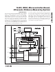
Figure 10. JTAG Interface Block Diagram
JTAG Interface
The joint test action group (JTAG) IEEE 1149.1 standard
defines a unique method for in-circuit testing and pro-
gramming. The MAXQ7667 conforms to this standard,
implementing an external test access port (TAP) and
internal TAP controller for communication with a JTAG
bus master, such as an automatic test equipment (ATE)
system. The MAXQ7667 JTAG interface does not allow
boundary scan. For detailed information on the TAP and
TAP controller, refer to IEEE Std 1149.1 “IEEE Standard
Test Access Port and Boundary-Scan Architecture” on
the IEEE website at www.standards.ieee.org.
The TAP controller communicates synchronously with
the host system (bus master) through four digital I/Os:
test mode select (TMS), test clock (TCK), test data
input (TDI), and test data output (TDO). The internal
TAP module consists of shift registers and a TAP con-
troller (Figure 10). The shift registers serve as transmit
and receive data buffers for a debugger. Maintain the
maximum TCK clock frequency to below 1/8 the system
clock frequency for proper operation.