
Instruction Manual


The BPF center frequency tracks B
FREQ
. The bandpass width is 14% of the center frequency (Q = 7). The 16-bit Echo Envelope
Bandpass Filter Input Data register (BPFI) and Echo Envelope Bandpass Filter Output Data register (BPFO) data are available in two’s
complement format at a data rate equal to 10 x B
FREQ
. The BPFI and BPFO registers are typically used only for debugging purposes.
They may not be synchronized to the CPU system clock and can only be reliably observed when the system clock is used as the
receive path clock.
A full-wave detector and LPF convert the AC output of the BPF to a DC value that represents the envelope of the echo waveform. The
output of the LPF in the Echo Envelope Lowpass Filter Output Data register (LPFD) is in straight binary format and is updated at a rate
equal to 5 x B
FREQ
. The output of the LPF can be read directly or it can be loaded into an 8-words deep FIFO.
The output of the LPF is automatically sent to the input of a 16-bit digital comparator. The comparator has a programmable threshold
level and can be used to detect the time at which the echo amplitude (LPF output) crosses a given threshold. This technique allows
for simple echo detection that can automatically stop a timer and generate an interrupt.
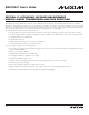
Figure 17-2 shows a block diagram of the echo receive path.
17-5 __________________________________________________________________________________________________________
MAXQ7667 User’s Guide
VARIABLE GAIN
SIGMA-DELTA
MODULATOR
BANDPASS
FILTER
TO SAR ADC
MUX
LNAAVDD/2
0V
2mV
P-P
TO EXTERNAL VOLTAGE
REFERENCE
USE TWO CAPS IN PARALLEL FOR LOW ESR.
RCVC.[7:6]:LNAISEL[1:0] RCVC.[4:0]:RCVGN[4:0]
LPFC.[2:0]:FFLS[2:0]
LPFC.[11:8]:FFDP[3:0]
LPFC.[15:12]:FFIL[3:0]
RCVC.8:LNAOSEL
BPFI[15:0]
RECV-CLOCK
APE.12:BGE
CLOCK
CONTROL
2.5V
BANDGAP REF
120kΩ
120kΩ
3kΩ
3kΩ
FULL-WAVE
RECTIFIER
AND
LOWPASS
FILTER
FIFO
CONTROL
COMPARATOR
AIN1AIN0
REFBG
REF
FIFO
8x16
0.47µF 0.47µF
0.47µF
AGND
AGND
BPFO[15:0]
LPFC.7:FFOV
LPFF.[15:0]
CMPC.15:CMPP
ASR.12:CMPLVL
FIFO IS FULL. AN ATTEMPT TO WRITE CREATES
THIS INTERRUPT.
ASR.2:LPFFL
CMPT[15:0]
LPFD[15:0]
AIE.1:LPFIE
ASR.1:LPFRDY
LPFC.3:FFLD
TIMER 0
TIMER 1
TIMER 2
DATA READY
INTERRUPT
AIE.2:LFLIE
CMPC[14:0]:CMPH[14:0]
ECHOP
ECHON
FUB
x1.0
AIE.3:CMPIE
ASR.3:CMPI
WHEN FFDP = FFIL, EXCEPT FOR FFIL = 0.
Figure 17-2. Echo Reception Stage